Video processor power supply, 20 zodiak installation planning guide installation, Figure 19. video processor frame, rear view – Grass Valley Zodiak Installation Planning Guide User Manual
Page 20
20
Zodiak Installation Planning Guide
Installation
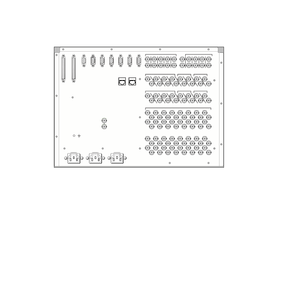
Power, control, and video connections are made at the rear of the Video
Processor frame.
shows the rear frame connectors.
Figure 19. Video Processor Frame, Rear View
Video Processor Power Supply
The Zodiak Video Processor frame houses up to three slide-in modules
rated at 400 watts each.
(See
).
Two hot-swappable power supply modules (primary and redundant) are
standard with the 2.5-M/E system, and three power supply modules are
standard with the 3-M/E system.
The power supplies load share such that a supply can fail and the Video
Processor frame will continue to operate.
It is recommended that each module’s AC input be connected to a separate
AC supply circuit. Any module(s) for which a separate supply circuit is not
available can be connected to an uninterruptible power supply (UPS).
Aux Outputs
Aux Outputs
Aux Outputs
Aux Outputs
PGM
PGM
PVW
PVW
M/E 2
M/E 2
M/E 1
M/E 1
Power Supply 1
Power Supply 1
AC
AC
Power Supply 2
Power Supply 2
AC
AC
Power Supply 3
Power Supply 3
AC
AC
Analog
Analog
Reference In
Reference In
64
64
63
62
62
61
61
60
60
59
59
58
58
57
57
56
56
55
55
54
54
53
53
52
52
51
51
50
50
49
49
48
48
47
47
46
46
45
45
44
44
43
43
42
42
41
41
40
39
39
38
38
37
37
36
36
35
35
34
34
33
33
32
32
31
31
30
30
29
29
28
28
27
27
26
26
25
25
24
24
23
22
22
21
21
20
20
19
19
18
18
17
17
16
16
15
14
13
13
12
12
11
11
10
10
9
8
7
6
5
4
3
2
1
Video Inputs
Video Inputs
M/E 3
M/E 3
PVW
PVW
PGM
PGM
PVW
PVW
PGM
PGM
13
13
12
12
11
11
10
10
9
8
7
6
Progra
Program /
m / Prese
Preset / DSK
DSK
Aux Outputs
Aux Outputs
Control
Control
Panel
Panel
Menu
Menu
Display
Display
J11
J11
J10
J10
J9
J9
J8
J8
J7
J7
J6
J6
J5
J5
J4
J4
J3
J3
J2
J2
J1
J1
PVW B
PVW B
PGM B
PGM B
PVW A
PVW A
PGM A
PGM A
Switched
Switched
Preview
Preview
5
4
3
2
1
CPL2
CPL2
CPL1
CPL1
Serial 4
Serial 4
Serial 3
Serial 3
Serial 2
Serial 2
Serial 1
Serial 1
Diag
Diag
Tally
Tally
GPI
GPI
8096_00_02_r2