19 adapter cable 17-pin with 14-pin pcb connector – HEIDENHAIN PWM 20 User Manual
Page 82
August 2014
Pin layouts
83
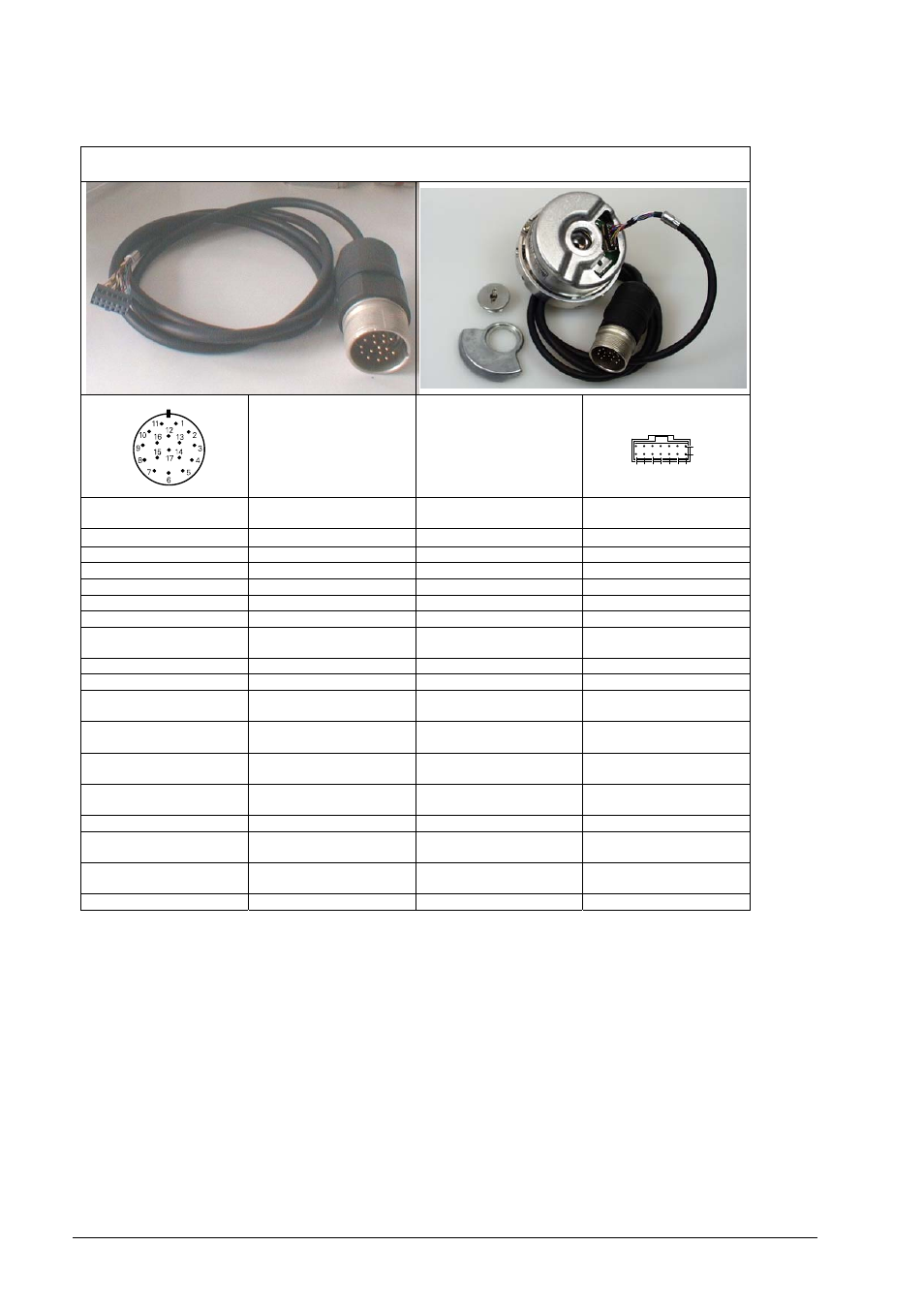
4.3.19 Adapter cable 17-pin with 14-pin PCB connector
TOP
1 2 3 4 5 6
a
b
7
Adapterkabel ID 330980-xx / Zn/Z1
Adapter cable ID 330980-xx / Zn/Z1
Signal
Farbe
Color
Kupplung 17-pol. Stift
Coupling 17-pin, male
Platinenstecker 14-pin
-
PCB connector 14-pin
PIN 1
U
P
– Sensor
blau / blue
7a
PIN 2
R-
schwarz / black
4a
PIN 3
R+
rot / red
4b
PIN 4
0V – Sensor
weiß / white
3a
PIN 5
Temp.+
grün / green
-
PIN 6
Temp. -
braun / brown
-
PIN 7
U
P
braun/grün
brown/green
1b
PIN 8
D-
violett /violet
6a
PIN 9
D+
gelb / yellow
/
2b
PIN 10
0V
weiß/grün
white/green
5b
PIN 11
Innenschirm
Internal shield
-
-
PIN 12
B+
blau/schwarz
blue/black
3b
PIN 13
B -
rot/schwarz
red/black
5a
PIN 14
C+
grau / grey
/
7b
PIN 15
A+
grün/schwarz
green/black
6b
PIN 16
A-
gelb/schwarz
yellow/black
2a
PIN 17
C-
rosa / pink
1a