Disc brake axle – ShoreLand'r PT2325AB User Manual
Page 7
Midwest Industries, Inc.
Ida Grove, IA 51445
800.859.3028
www.shorelandr.com
0003964
Page 7
05/14/2008
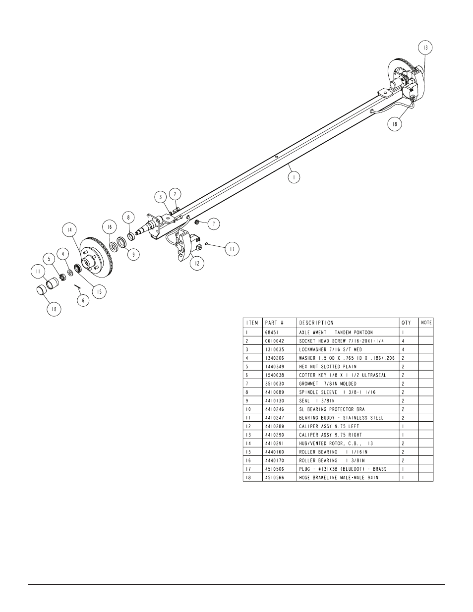
AXLE
Place one of the spring bracket bushings into the rear of the spring
bracket and secure with a 9/16” x 3 1/4” hex bolt and hex lock nut.
Repeat in other spring bracket. Position the axle under the frame,
then hook the loop end of the spring around the bushings just in-
stalled. Note that if the axle is positioned too low when trying to
hook, the loops will not hook around the bushings.
Raise the front of the springs up so they align with the front hole
of the spring bracket. Secure in place with 9/16” X 3-1/4” hex bolts
and lock nuts. Repeat this process on the other spring.
Tighten all axle U-bolts and spring bolts not tightened at this time.
NOTE: The axle has brake fluid installed in the clusters and the
axle line when it is assembled at the factory. This is done to protect
the inner parts of the brake system during shipping and storage.
The complete brake system including the axle
MUST be re-bled to
ensure that all air has been removed from the brake system.
Disc Brake Axle
CONNECTING THE TONGUE & SIDE FRAME BRAKE LINES
Locate the brass brake line coupling. Remove the plastic caps from
the ends of both the tongue and side frame brake hoses and thread
them into the coupling. Tighten. Push the remaining brake hose
either back into the tongue or the side frame. Re-install the rubber
grommet into the side frame if removed during connection of the
brake hoses.
ONE AXLE BRAKE INSTALLATION
Locate the hose mounting bracket provided in the kit. Note that the
strap has several holes. Remove the lock nut from the inside leg of
the right rear spring bracket U-bolt. Slip the 9/16” hole in the hose
mounting bracket over the U-bolt leg and replace the lock nut just
removed. Tighten. This bracket is used to secure the brake hose as
it is routed down to the axle.
Remove the remaining brass plug from the brass block located on
the right caliper. Pull the frame brake line hose out of the side frame
enough so it can be routed down through the large hole in the brake
hose clip just installed and then down to the brass block where the
plug was just removed.
Thread the end of the brake hose into the port from where the plug
was removed earlier and tighten according to the tightening instruc-
tions. Pull the excess hose back up through the hole in the brake
hose clip leaving only enough slack in the hose to allow for the
full movement of the axle when towing. Place a rubber grommet
around the brake hose and insert it into the hole in the brake hose
clip.
Push all excess hose back into the side frame. Secure the brake
hose to the inside of the side frame using either one or two of the
round brake hose clips and self-tapping screws provided. Space
the hose clips so they are evenly spaced from the side frame hole
to where the hose is positioned in the brake hose clip.
Fill the actuator reservoir with brake fluid and bleed the brake sys-
tem per the bleeding instructions in one of the following: UFP Brake
Bleeding Manual or the ShoreLand’r Disc Brake Manual. Once
bled, refill the reservoir and replace the reservoir cap.
TIRE & WHEEL ASSEMBLIES
Mount the tire and wheel assemblies using the ½” fine threaded
tapered lug nuts provided. Tighten to 85-95 ft/lb. of torque using the
rotation pattern as shown in the ShoreLandr’s Owners Manual.
Re-torque the lug nuts after 50 miles of driving and then periodi-
cally thereafter.