SMA 485 Data Module Type B User Manual
Page 16
5 Electrical Connection
SMA Solar Technology AG
16
485BRD-10-IA-en-12
Installation Manual
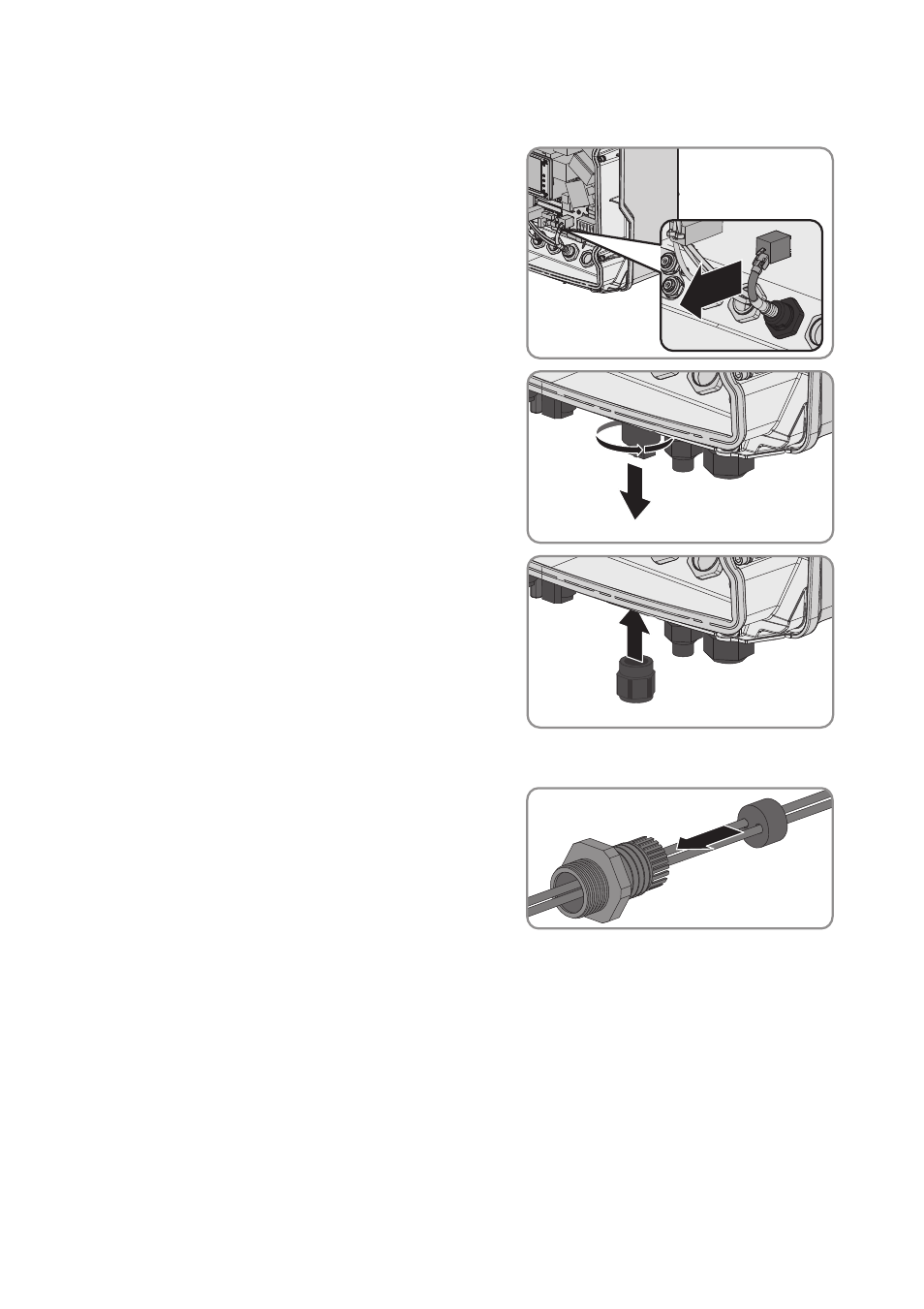
Mounting and Preparing the Supplied Cable Gland on the Inverter
1. Remove the plug from the Ethernet socket.
2. Unscrew the Ethernet socket from the enclosure
opening.
3. Insert the supplied M25 cable gland in the
enclosure opening and tighten it from the inside
using the counter nut (torque: 3.5 Nm ± 0.3 Nm).
4. Unscrew the swivel nut from the cable gland and remove the sealing plug from the cable gland.
5. Remove the cable support sleeve with one hole
from the M25 cable gland and insert the cables
into the supplied cable support sleeve with two
holes.
6. Press the cable support sleeve into the cable gland and lead each cable all the way up to the
sockets on the 485 data module.
7. Screw the swivel nut onto the M25 cable gland.
8. Remove the protective cover of the multi-function relay from the inside of the inverter.
The protective cover is no longer required.