3 connecting the 485 data module – SMA 485 Data Module User Manual
Page 14
5 Connection
SMA Solar Technology AG
14
485i-Module-IA-en-18
Installation Manual
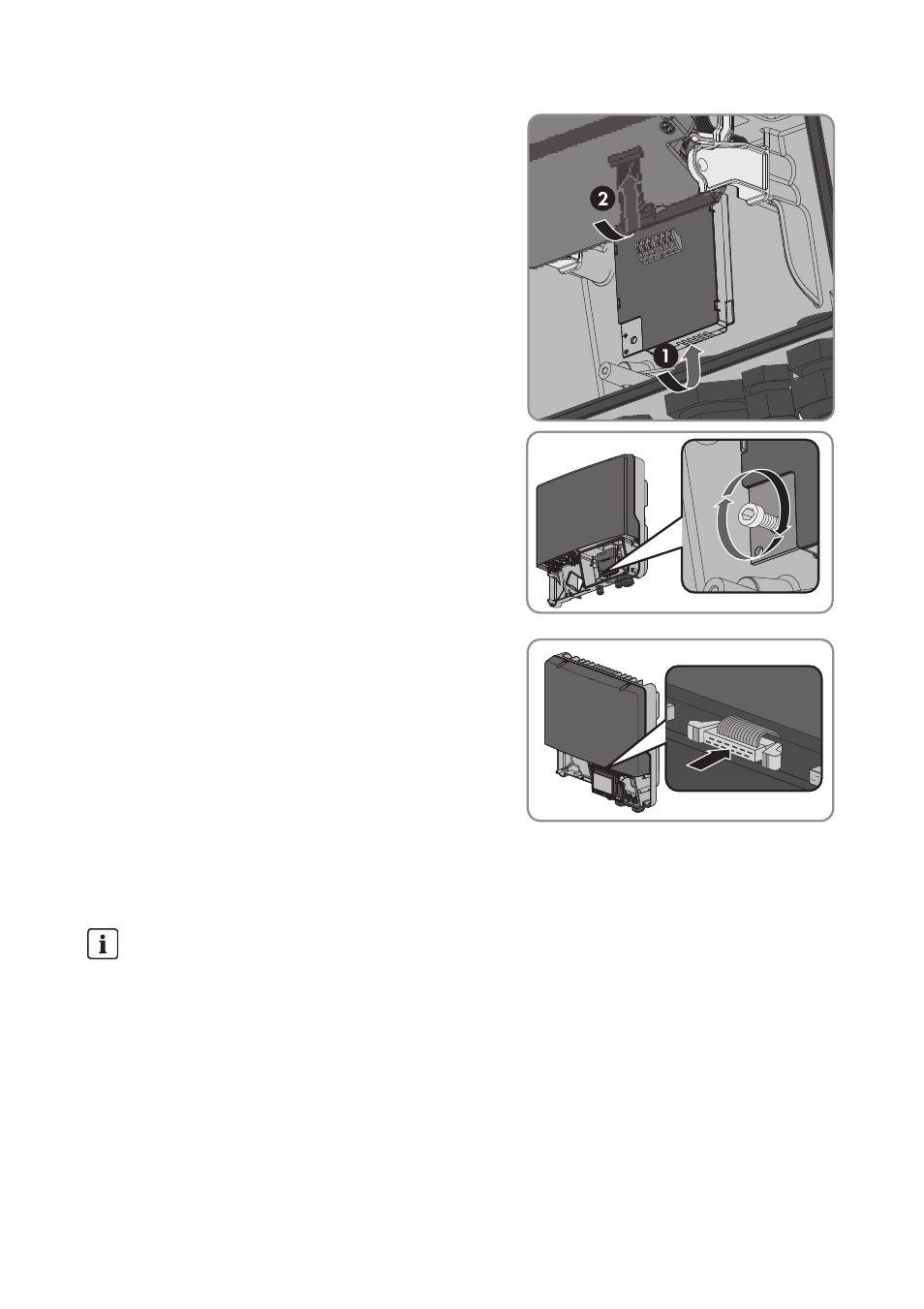
6. Insert the 485 Data Module and slide the ribbon
cable upwards behind the display. The key on the
top edge of the 485 Data Module must fit into the
hole in the plastic retainer in the inverter.
7. Fasten the 485 Data Module hand-tight with the
hexagon socket screw (AF 3, torque: 1,5 Nm).
8. Flip down the display.
9. Plug the ribbon cable plug onto the centre
connector strip.
5.3 Connecting the 485 Data Module
To achieve a good signal quality, observe the cable recommendation (see technical description
"RS 485 Cabling Plan")
During operation, AC cables generate an electromagnetic field which may induce interference
in plant communication.
Disturbance of Data Transmission due to AC Cables
• Lay the RS485 communication cables using suitable fastening material and with a
minimum clearance of 50 mm to the AC cables.