SMA 485 Data Module User Manual
Page 16
GND
5
5
Data+
2
2
Data-
7
7
5 Connection
SMA Solar Technology AG
16
485i-Module-IA-en-18
Installation Manual
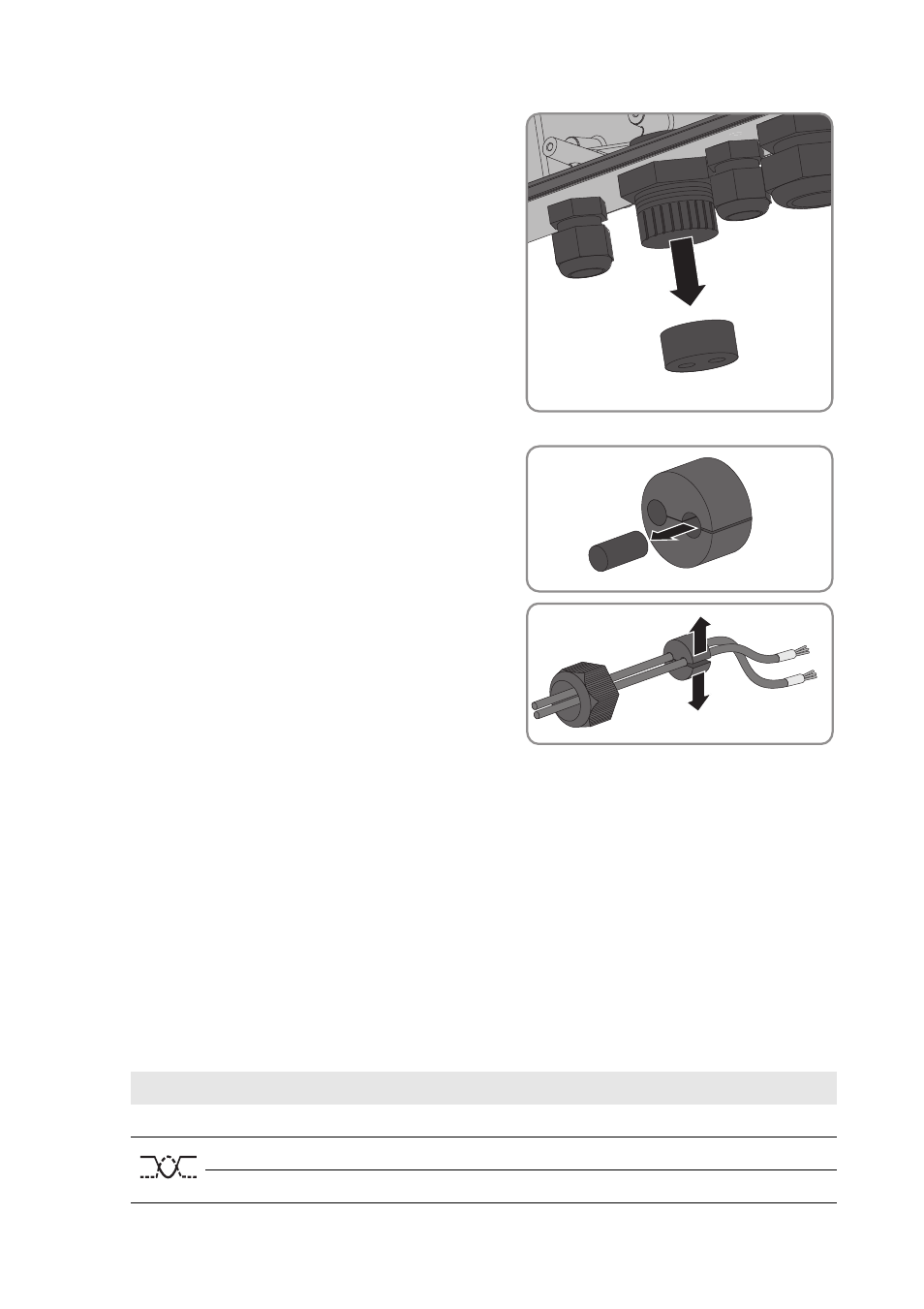
3. Press the seal out of the cable gland from the inside.
4. Route the cable from the outside into the inverter
through the loose swivel nut and the cable gland.
5. Remove one of the filler-plugs from the seal for each
cable.
6. Insert the cable into the seal.
7. Push the seal into the cable gland. Make sure that
any unused cable openings are sealed with filler-plugs.
8. Screw the swivel nut of the cable gland on lightly.
9. Remove or connect the terminator:
• If two cables are connected, open the spring clamp terminals of the plug with the connected
terminator and remove the terminator.
• If one cable is connected, the terminator in the unused plug must be connected in terminals
2 and 7.
10. Open the spring clamp terminals on the plug.
11. Connect the wires to the plug terminals and note down the colour of the wires. The cables can
be allocated to any plugs of your choosing.
Signal
485 Data Modules
RS485 bus Insulated wire colour