3 electronic solar switch (ess), 1 assembly, Electronic solar switch (ess) – SMA ESS User Manual
Page 8: Assembly
Electronic Solar Switch (ESS)
SMA
Technologie AG
8
ESS-BEN074812
User manual
3 Electronic Solar Switch (ESS)
With the Electronic Solar Switch, disconnecting the inverter becomes a three-step pro-
cess.
1.
Disconnecting the AC side
2.
Pulling the Electronic Solar Switch.
3.
Disconnecting the DC plugs
If the Electronic Solar Switch is not pulled off, removal of the DC plug connectors can
cause arcing, which may cause personal injury and may damage the inverter connec-
tors. Section 4 „Operating the Electronic Solar Switch” (Page 10) describes how to dis-
connect the DC side.
3. 1 Assembly
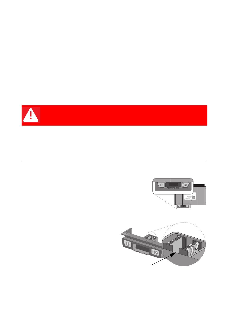
The Electronic Solar Switch consists of a handle on the un-
derside of the inverter, and a module inside the inverter.
A handle, which covers the plugs on the solar generator,
is mounted on the underside of the inverter.
There is a plug inside the handle. The plug
of the Electronic Solar Switch is only visi-
ble when the handle is pulled out.
The plug is fitted in the handle as a float-
ing connector, so that the handle does not
catch when pulled from the inverter.
DANGER!
Risk of lethal electric shock!
Safe disconnection from the solar generator can only be guaranteed once the
Electronic Solar Switch handle and all DC plug connectors have been pulled
off.
•
After pulling off the Electronic Solar Switch, immediately disconnect all
DC plug connectors.
Electronic Solar Switch handle
Plug