SMA CLUSTER CONTROLLER Installation User Manual
Page 65
Pin group
Pin
Signal
Explanation
Analog current output 2
Feedback for current reactive power
setpoint
A4
I+
Current output
A5
I−
Current return
A6
GND
Shield ground
Analog current output 3
Feedback for current total active
power of the system as a percentage
of the maximum nominal system
power
B1
I+
Current output
B2
I−
Current return
B3
GND
Shield ground
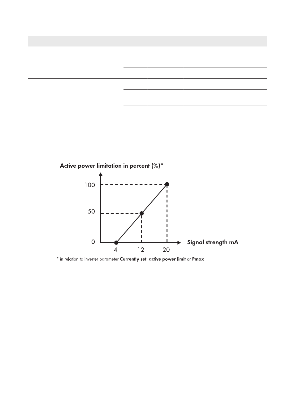
Interpretation of the Signal Strength as a Percentage Value of the Active Power
Limitation
The strength of the feedback signal corresponds to the percentage value to which the active power
of the inverters in the system is currently limited.
Figure 28: Interpretation of the signal strength as a percentage value of the active power limitation in relation to
the inverter parameter Currently set active power limit or Pmax
6 Connection and Commissioning
SMA Solar Technology AG / SMA America, LLC
Installation Manual
65
ClusterController-IA-en-14