SMA SB 2800i Installation User Manual
Page 31
Installation Guide
Communication
SB2800i-11:SE0504
SMA Regelsysteme GmbH
29
6. Connect the wires of a cable to the terminals on the commu-
nication slot with the same allocation as written down for the
first inverter. This applies both to the wires in the cable
coming from the last inverter and in the one running to the
next inverter. Proceed with special care! Finding wiring
failures can be very frustrating!
7. Repeat points 5 and 6 for each Sunny Boy to be connected.
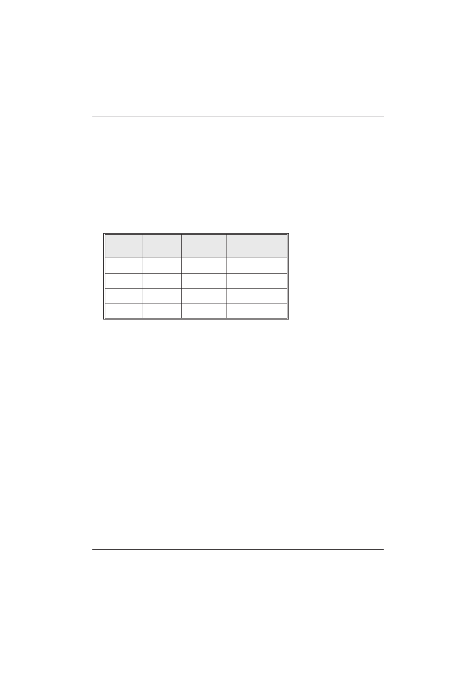
8. To be able to connect them to a Sunny Boy Control or a PC
with an interface converter later, label the wires at the end of
the cable as follows.
The connection of one or several Sunny Boy inverters to a
Sunny Boy Control is described in detail in the manual of the
Sunny Boy Control.
Terminal
D-SUB 9
plug
Labeling of
wire
Your wire
labeling
Enclosure
Enclosure
Shielding
2
3
Data +
7
8
Data -
5
5
GND