2 interior view, Interior view – SMA SB 2500 Installation User Manual
Page 21
Advertising
SMA Solar Technology AG
Electrical Connection
Installation Manual
SB25-30-IA-en-51
21
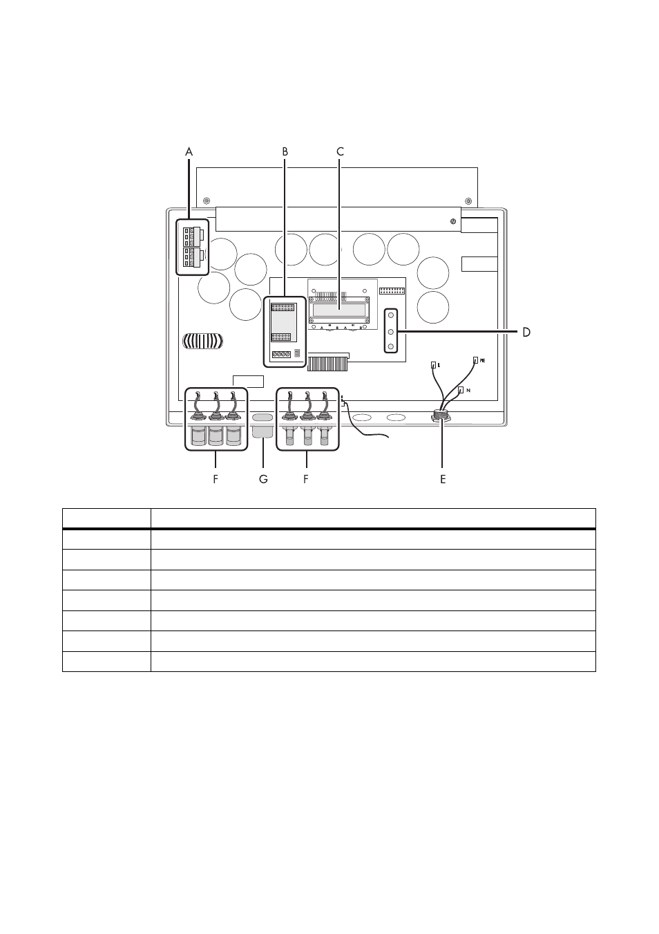
5.1.2 Interior View
The following figure shows the various components and connection areas of the open inverter.
* If you have ordered the inverter without ESS, the inverter is equipped with 1 negative and 1 positive DC connector.
** Optional
Object
Description
A
Varistors
B
Connection area and slots for optional communication via RS485
C
Display
D
Operating status LEDs
E
Jack for AC connection
F
DC connector*
G
Jack for the Electronic Solar Switch (ESS)**
Advertising
This manual is related to the following products: