5 connecting the cables in the sunny central, Connecting the cables in the sunny central, Connection to terminals – SMA VOLTAGE STABILIZER User Manual
Page 20
5 Electrical Connection
SMA Solar Technology AG
20
Ukonstanter-IEN103610
Installation Guide
5.5 Connecting the Cables in the Sunny Central
Overview of the Connection Area in the Sunny Central
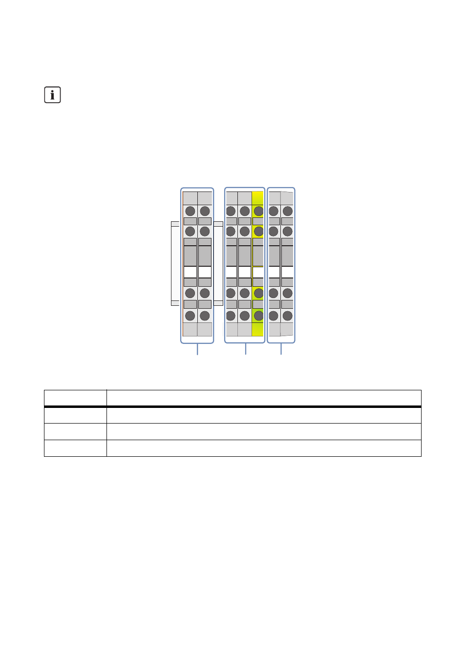
Figure 10: Connection terminal strip in the Sunny Central, examples shown here are for options 2/0 and 5/5
Connection to Terminals
• All connection terminals that are not being used must be screwed tightly.
• Strip 5 mm from the cable insulation.
• Observe the following torques when connecting the cables to the terminals:
Circuit Diagram
For all electrical connections, it is imperative that you use the provided Sunny Central circuit
diagram. The exact position of the terminal strip can be determined with the help of the
reference designation.
Object
Description
A
Temperature monitoring
B
230 V circuit
C
415 V circuit
M3
0.6 … 0.8 Nm
M4
1.5 … 1.8 Nm
M6
3.2 … 3.7 Nm
5
4
3
2
1
2
1
A
C
B
Z120
-X
120
Z121
-X
121