JBL Synthesis S3900 User Manual
Page 5
5
www.jbl.com
E
ngli
sh
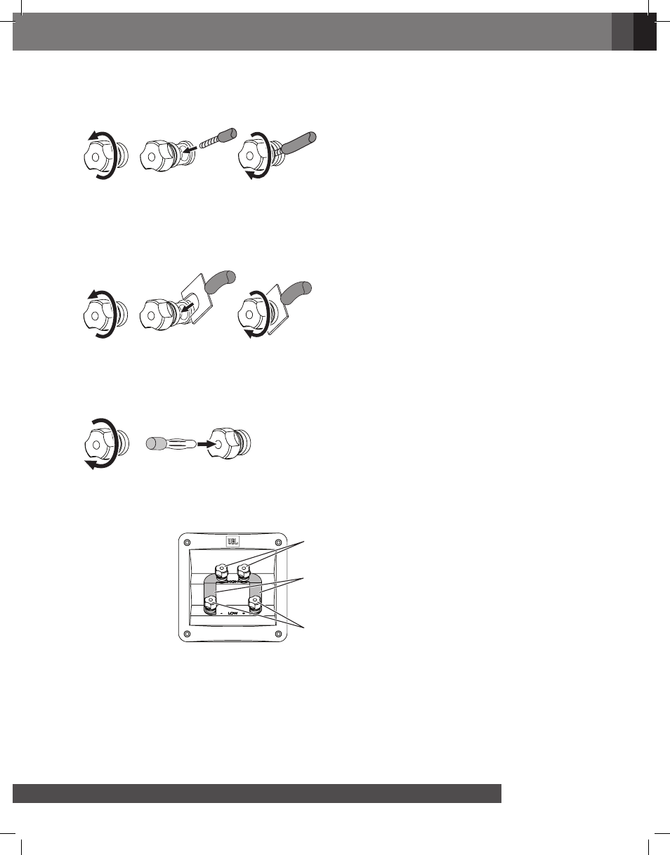
Using Bare Wire or Pin Connectors:
A. Unscrew Cap
B. Insert Bare Wire
or Pin Connector
through Hole in Post
C. Tighten Cap
to Secure Wire
IMPORTANT: Make sure the “+” and “–” wires or pins do not touch each other or the other connector. Touching wires
can cause a short circuit that can damage your receiver or amplifier.
Using Spade Connectors:
A. Unscrew Cap
C. Tighten Cap to
Secure Spade
Connector
B. Insert Spade
Connector Blades
around Post
IMPORTANT: Make sure the “+” and “–” spade connector blades do not touch each other or the other connector.
Touching blades can cause a short circuit that can damage your receiver or amplifier.
Using Banana Connectors:
A. Tighten Cap
B. Insert Connector
BI-WIRE CONNECTION:
The S3900 connection assembly has two sets of input connectors that are connected by jumper bars. The upper set
of connectors is for the high-frequency/ultrahigh-frequency drivers, and the lower set of connectors is for the woofers.
High-Frequency/
Ultrahigh-Frequency
Connectors
Low-Frequency
Connectors
Jumper
Bars
This arrangement allows you to bi-wire the speakers using a single stereo power amplifier or to bi-amp the speakers
using two stereo power amplifiers. Bi-wiring and bi-amping can offer performance advantages and more flexibility in
power-amplifier selection over a conventional single-wire connection.
NOTE: The hole in the connector post is
5mm in diameter. Please use speaker cable
or a connector pin with an external diameter
of less than 5mm.
NOTE: The connector post is 8mm in
diameter. Please use a spade connector
with an inside diameter of more than 8mm.