Jordan Valve Mark 50 Series – Self-Operated Back Pressure Regulator User Manual
I & m mark 50 (2½” - 4”), Protect valves with line strainers, Installation
3170 Wasson Road • Cincinnati, OH 45209 USA
Phone 513-533-5600 • Fax 513-871-0105
[email protected] • www.jordanvalve.com
I & M Mark 50 (2½” - 4”)
Installation & Maintenance Instructions for
Mark 50 (2½” - 4”) Back Pressure Regulator
Warning: Jordan Valve Pressure Regulators must only be used, installed and repaired in accordance with these In-
stallation & Maintenance Instructions. Observe all applicable public and company codes and regulations. In the event
of leakage or other malfunction, call a qualified service person; continued operation may cause system failure or a
general hazard. Before servicing any valve, disconnect, shut off, or bypass all pressurized fluid. Before disassembling
a valve, be sure to release all spring tension.
Please read these instructions carefully!
Your Jordan Valve product will provide you with long, trouble-
free service if it is correctly installed and maintained. Spending
a few minutes now reading these instructions can save hours
of trouble and downtime later. When making repairs, use only
genuine Jordan Valve parts, available for immediate shipment
from the factory.
Installation
1.
To protect the regulator from grit, scale, thread chips,
and other foreign matter, all pipe lines and piping com-
ponents should be blown out and thoroughly cleaned
before the regulator is installed.
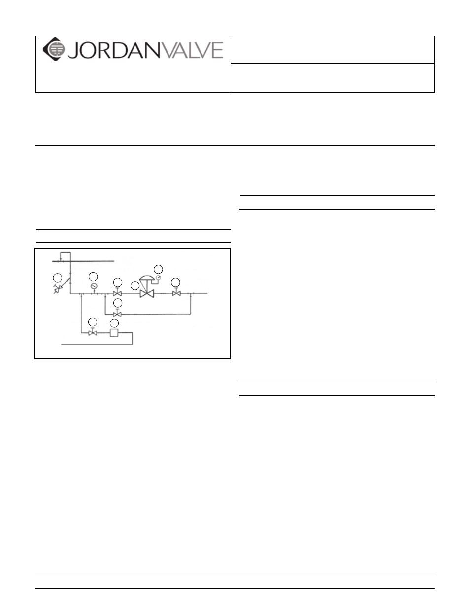
2.
Shut-off valves, pressure gauges, and by-pass piping
should be installed as indicated in the diagram to provide
easier adjustment, operation, and testing.
3.
A line strainer should be installed on the inlet side of the
regulator to protect it from grit, scale and other foreign
matter. A 0.033 perforated screen is usually suitable.
Line strainers are available from Jordan Valve.
4.
Install the regulators in the highest horizontal line of pip-
ing to provide drainage for inlet and outlet piping, to pre-
vent water hammer, and to obtain faster regulation.
5.
The flow arrow on the regulator body must be pointed in
the direction of flow. The regulator may be installed verti-
cally or horizontally without affecting its operation.
6.
For best control, a minimum 3’ 0” straight section of pipe
should be installed on either side of the regulator.
7.
In hot vapor lines, upstream and downstream piping near
the regulator should be insulated to minimize condensa-
tion.
8.
Expand the outlet piping at least one pipe size if the out-
let pressure (downstream) is 25% of the inlet pressure
or less. A standard tapered expander connected to the
outlet of the regulator is recommended.
9.
Where surges are severe, a piping accumulator is recom-
mended.
Control Line
A control line must be installed as follows:
1.
Connect one end of a 3/8” control line to the 3/8” NPT
tapped opening in the underside of the lower spring
housing.
2.
Connect the other end in a straight run of pipe 3 to 5 feet
upstream from the regulator.
3.
Do not locate the control line tap in an elbow, swage, or
other changes in configuration of the pipeline where tur-
bulence or abnormal velocities may occur.
4.
The control line should be sloped away from the regula-
tor.
5.
Install a shut-off valve (not a needle valve) in the control
line.
6.
Install a pressure gauge in the control line or near the
inlet of the regulator to aid in setting the regulator and
checking for inlet pressure during maintenance proce-
dures. (There is a ¼” NPT tapped opening in the lower
bonnet.)
Start-Up Procedure
With the inlet and outlet shut-off valves closed:
1.
Throttle the bypass valve so that the pressure to be con-
trolled is maintained near the set point.
2.
Fully open the control line shut-off valve.
3.
Slowly open the inlet shut-off valve.
4.
Open the outlet shut-off valve.
5.
Slowly close the bypass valve, but do not close it fully
until you are certain that the regulator has control of the
system.
6.
To change the controlled pressure, turn the adjusting
screw clockwise to increase pressure, counter-clockwise
to decrease pressure.
7.
WARNING: Never substitute a longer length adjusting
screw. Personal injury and damage to the valve my result.
8.
Body-cap cap screws should be retightened to 90 ft./lbs.
torque after valve reaches operating temperature.
1. Shut-Off Valve
2. Jordan Regulator
3. Strainer & Drain Valve
4. Pressure Gauge
5. Steam Trap
4
1
1
5
1
3
4
1
2
Main Line
Condensate Return
PROTECT VALVES WITH LINE STRAINERS