Stroke adjustment, Torque procedure for cap and spring housing bolts, Ordering spare parts – Jordan Valve Mark 50 Series – Self-Operated Back Pressure Regulator User Manual
Page 3
-3-
5.
Check the condition of and clean all parts. Clean the
lower stem bushing. Replace defective parts.
6.
Reassemble in reverse order and follow the procedures
outlined under STROKE ADJUSTMENT.
Stroke Adjustment
1.
Do not tighten locknut on the stem; run it to the upper
end of the thread with the disc pin located at about the
center of the threaded section. The valve stroke adjust-
ment is determined by how far the diaphragm assembly
is threaded onto the stem. Holding the stem lightly with
pliers, thread the diaphragm assembly approximately
four turns onto the valve stem and center the disc pin in
the valve body. Tighten locknut.
2.
Place the plate in the valve body so that the disc pin
protrudes through the center slot. The marking “TOP DI-
RECT” must be toward the diaphragm. Use new gaskets.
Follow the same precautions as outlined under SEAT
REMOVAL.
3.
Temporarily place the disc on the disc pin so that its ar-
row points (^) toward the diaphragm. Hold parts so they
do not fall out.
4.
Push the diaphragm assembly down, against the valve
body and check the orifice alignment of the disc and
plate. The orifices should be fully open and in perfect
alignment.
5.
If the orifices are not in perfect alignment, rotate the
diaphragm assembly counterclockwise to lower the valve
disc, or clockwise to raise the valve disc.
6.
Remove the disc, turn 180o, and reinstall with the arrow
(v) pointing away from the diaphragm. The seats are now
fully closed with overlap.
7.
Install the upper bonnet and fasten with two bolts 180°
apart. If metal diaphragms are used, be certain they are
in the recess.
8.
Carefully use a tool to pry up on the disc pin, from the
opposite end of the valve, and stroke the stem upward
until the upper diaphragm plate stops against the hous-
ing.
9.
The orifices should be fully open and in perfect align-
ment. If they are not, you will have to remove the upper
housing and rotate the diaphragm assembly as in step
(5). Then repeat steps (7), (8) and (9).
10. The total stroke of the MARK 50 BPRV is equal to the
orifice width plus 1/16” overlap. Consequently, perfect
adjustment is required for proper operation.
11. After proper adjustment has been obtained, remove the
valve plate and valve disc to eliminate the possibility of
damage during topworks reassembly.
12. Place adjusting spring, spring seat and ball bearing on
the upper diaphragm plate.
13. In replacing the upper spring housing, make certain that
it seats properly in the recess. Torque 9/16” bolts to 100-
125 ft./lbs.
14. Reinstall the disc and plate. The wording “Top Direct” on
the plate should be on top and the arrow on the disc
should point towards the plate wording “Top Reverse.”
15. Install the cap onto the body. Align the cap and body
flange holes. Install the cap screws and tighten them uni-
formly to 90 ft./lbs.
16. Adjust adjusting screw to the approximate position it was
in.
17. Reinstall and follow START-UP PROCEDURE.
18. Retighten body cap screws after the valve has been rein-
stalled and has reached operating temperature.
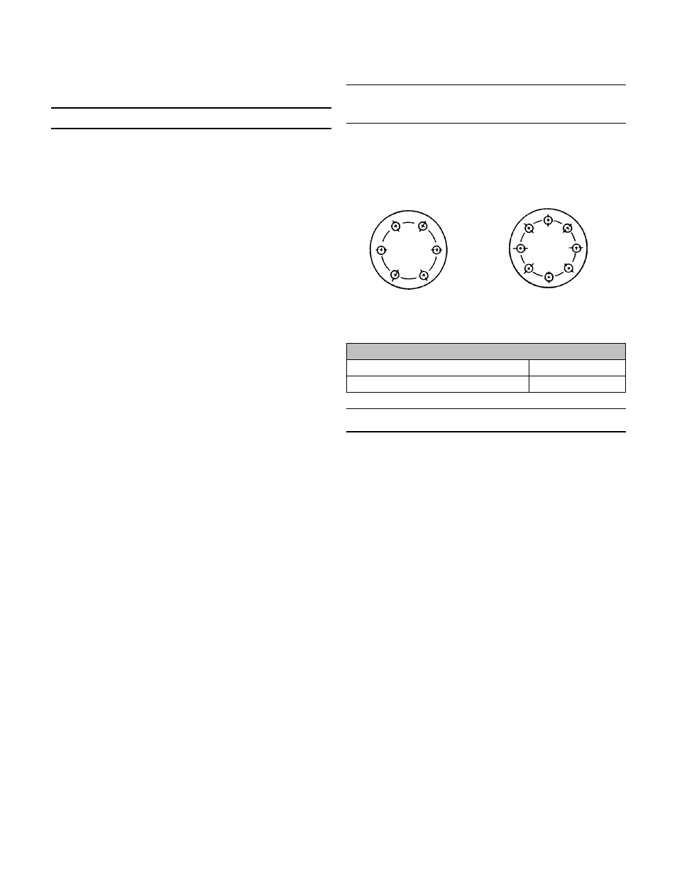
Torque Procedure for Cap and
Spring Housing Bolts
1.
Install all bolts hand-tight.
2.
Torque the bolts in order of the bolt pattern to a value
equal to ¼ of the recommended torque value.
3.
Re-torque each bolt to the recommended value using
the same bolt pattern as shown.
Recommended Bolt Torque
Body to Cap
90 ft./lbs.
Spring Housing
85 ft./lbs.
Ordering Spare Parts
Use only genuine Jordan Valve parts to keep your valve in good
working order. So that we can supply the parts which were de-
signed for your valve, we must know exactly which product you
are using. The only guarantee to getting the correct replace-
ment parts is to provide your Jordan Valve Representative with
the valve serial number. This number is located on the valve
identification tag. If the serial number is not available, the parts
needed for your valve might be able to be determined with the
following information: Model Number, Valve Body Size, Seat
Material and Cv rating, Spring Range and Set Point, Trim Mate-
rial, Part Name - Number and Quantity (see parts list chart).
NOTE: Without a valve serial number, any parts ordered incor-
rectly are subject to up to a minimum 25% restock charge
when returned.
5
3
1
6
4
2
5
3
1
6 4
2
7
8
6 bolts
(or multiples)
8 bolts
(or multiples)