Start-up procedure, Trouble shooting, Valve seats – Jordan Valve Mark 56 Series – Air Loaded Back Pressure Regulator User Manual
Page 2
Disc Pin
Disc Spring
Lockwashers
Body
Bolts
Body
Gasket: Plate-Body
Plate
Disc
Cap
Gasket: Cap-Plate
Disassemby (All Sizes)
The sliding gate valve seat is the key to the excellent
control and tight shutoff provided by a Jordan valve.
Maintaining these seats in good condition is critical to
valve performance, so care in handling is imperative.
NEVER USE METALLIC OBJECTS IN REMOVING THE
SEATS. Improper handling can result in leakage and poor
control.
1.
Close the shutoff valve on each side of the valve,
and remove the valve from the line.
2.
Note scribed “<“ on the side of the body and cap
for 1/2” - 2” sizes. Secure the body in a vise. Re-
move the body bolts and stud nuts and lift the cap
straight up.
3.
Before removing, note the locating pin that aligns
the plate with the disc guide on 1/2” to 1-1/2”
sizes. This pin should be on the same side as the
“<“ on the body and cap. Remove the plate and
disc (on 2” valves, the disc will be attached to the
plate, and the screws should now be removed to
separate the two parts; on 2-1/2” - 6” valves, place
the body on its side to remove the plate). Place the
disc on the bench with lapped surfaces facing up.
Protect the lapped surfaces on both sides of the
disc guide.
It is important that the disc pin is not rotated when
disassembling, cleaning, or reassembling, since this af-
fects the stroke adjustment.
4.
Lightly tap on the body to remove the disc guide (2”
valve uses a pressure ring instead of a disc guide).
Invert the body, let the disc guide drop out into
Start-Up Procedure
With the inlet, outlet and bypass shutoff valves
closed, and no pressure in the downstream line:
1.
Fully open the control line shutoff valve.
2.
Fully open the outlet shutoff valve.
3.
Slowly open the inlet valve just enough to start
flow through the regulator. Observe the upstream
pressure gauge. Increase the air-loading pressure
slowly to gradually close the regulator.
4.
Do not fully open the inlet valve until you are sure
that the regulator has control of the system. Usu-
ally, the handwheel on the inlet valve will turn freely
when this point is reached.
5.
To change the controlled pressure, adjust the load-
ing pressure supplied to the top of the diaphragm.
Trouble Shooting
Erratic Control
•
Oversizing causes cycling and hunting, and re-
duces the rangeability of the regulator. Check siz-
ing calculations to be sure that you have the proper
size valve.
•
Steam traps downstream may need attention and
could be causing erratic control.
•
Safety valve may be jammed open, disrupting the
system. Repair as necessary.
•
Excessive foreign matter on seats can cause erratic
operation. Clean them as outlined under Valve
Seats.
•
Valve stroke may be out of adjustment. Readjust
stroke.
•
Valve disc may not be moving freely. Check disc
guide clearance, and clearance of the stem to the
bushings.
Will Not Operate
•
Diaphragm may be ruptured and need replace-
ment.
Valve Seats
-2-
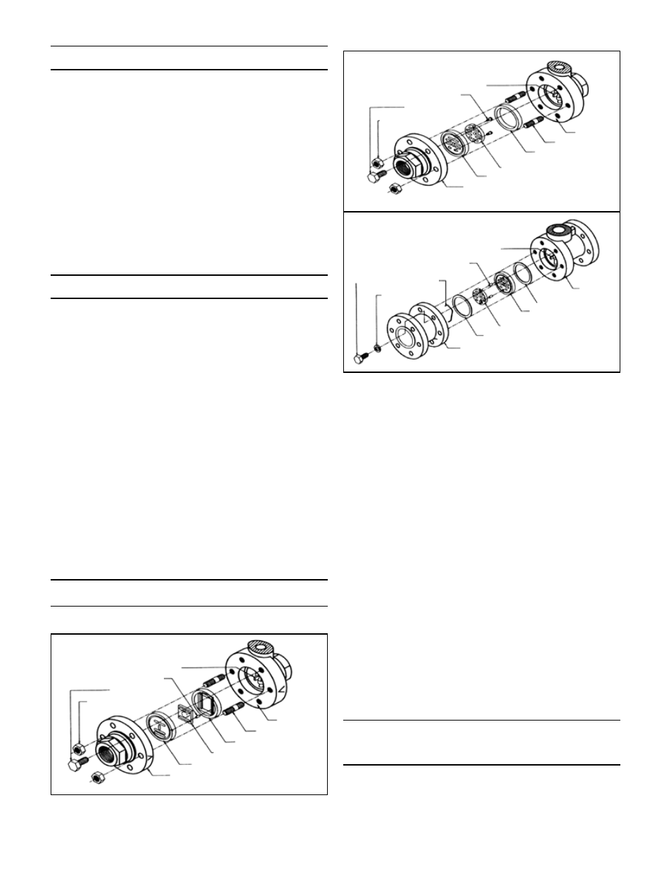
Disc Pin
Index Pin
Body Bolts
Stud Nuts (2)
Body
Studs (2)
Disc Guide
Disc
Cap
Plate
Disc Pin
Guide Screws (2)
Body Bolts
Stud Nuts (2)
Body
Studs (2)
Pressure Ring
Disc
Cap
Plate
Disc Guide (2)
1/2” to 1-1/2”
2”
2-1/2” to 6”