Table 2: outlet pressure ranges, Table 3: wide-open flow coefficients – Jordan Valve Mark 630 Series - Gas Service/High Pressure Regulator User Manual
Page 3
-3-
Disconnect vent line if installed.
2.
Unscrew two cap screws (9) and four cap screws
3.
(10) with hex nuts (25).
Remove the spring housing (3).
4.
Remove from the lever assembly, as a unit, the dia-
5.
phragm (11), connector head assembly (12), lower
spring guide (7) and cap screw (6).
Unscrew the cap screw (6) from the connector
6.
head (12) and disassemble the diaphragm (11).
Install a new diaphragm, making sure that it is
7.
properly centered. Reassemble connector head
assembly and lower spring guide, securely tight-
ened with the cap screw.
Engage connector head in lever assembly.
8.
Reinstall the spring housing with cap screws and
9.
nuts finger-tight only. Assure proper diaphragm
slack by slightly compressing the spring with the
adjusting screw (tighten by turning clockwise). Fi-
nally, complete the tightening of all cap screws and
nuts.
Table 1: Maximum Pressure and Pressure Drops
Port Diameter
1/8”
1/4”
3/8”
1/2”
Max. Allowable Inlet
Pressure, psig
1
1500
1500
1000
750
Max. Allowable Pressure
Drop, psid
1500
1000
500
250
† The sum of the outlet pressure setting and the maximum allowable pressure
drop determines the maximum allowable inlet pressure for a given installation.
For example, with a 3/8” seat ring orifice (maximum pressure drop of 500 psi)
and a 275 psig outlet pressure setting, the maximum inlet pressure is 775 psig
(500 psi + 275 psi + 775 psi).
Table 2: Outlet Pressure Ranges
Outlet Pressure
Range psig
27-50
46-95
90-150
150-200
200-275
275-500
Max Outlet
Pressure over
Pressure
Setting †, psig
200
200 ‡
Max Emergency
Outlet (Casing)
Pressure, psig
550
† Internal parts of the regulator may be damaged if the outlet pressure
exceeds the pressure setting beyond the amounts shown.
‡ This applies to outlet pressure settings below 350 psig only. For pressure
settings above 350 psig, outlet pressure is limited to 550 psig, the maximum
emergency outlet (casing) pressure.
Table 3: Wide-Open Flow Coefficients
Orifice Size
C
g
C
v
C
1
1/8”
13.9
0.49
28.4
3/16”
31.3
1.11
28.2
1/4”
55.1
2.03
27.2
3/8”
122.5
4.61
26.6
1/2”
216.0
8.18
26.4
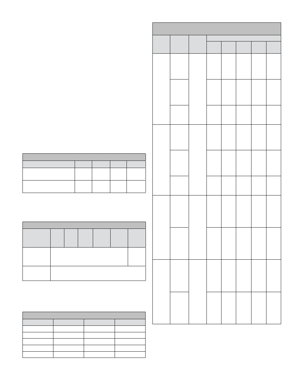
Table 4: High Pressure Regulator Flow Capacities (scfh of
0.6 Specific Gravity Gas; based on 20% Droop)
Outlet
Pressure
Range
psig
Inlet
Pressure
psig
Outlet
Pressure
psig
Seat Ring Orifice Diameter (inches)
1/8
3/16
1/4
3/8
1/2
27-50
60
50
900
2000
3100
5200
8100
75
1300
28500
3800
7200
10000
100
1700
3500
5700
10500
13000
150
2600
5700
8700
13000
17000
200
3500
7800
11000
16000
19000
300
5300
10500
14000
20000
23000
400
6900
13000
17000
23000
―
550
9600
16000
20000
26000
―
600
9800
17000
21000
―
―
1050
17000
23000
27000
―
―
1500
19000
25000
―
―
―
46-95
60
50
800
1500
2400
4300
6400
75
1200
2100
3100
5500
8000
100
1500
3100
4200
7500
10000
150
2400
4500
6700
11000
14000
200
3400
6600
9400
14000
17000
300
5200
8900
11000
16000
20000
400
6800
11000
15000
20000
―
550
9500
13000
17000
23000
―
600
9800
14000
19000
―
―
1050
14000
19000
22000
―
―
1500
18000
24000
―
―
―
46-95
100
75
1700
3200
5000
8000
13000
125
2200
4300
6700
10000
15000
200
3500
7300
10000
16000
22000
250
4400
9400
1300
19000
24000
325
5700
11000
16000
23000
27000
400
7100
14000
19000
27000
―
575
9700
18000
23000
30000
―
600
9900
19000
25000
―
―
1075
18000
27000
32000
―
―
1500
23000
32000
―
―
―
90-150
125
100
2000
3600
5500
9200
13000
150
2500
4600
6800
11000
16000
200
3600
6600
9400
13000
22000
250
4400
8500
11000
18000
26000
300
5300
9800
14000
21000
30000
350
6100
10000
16000
25000
32000
400
7000
13000
18000
27000
―
600
9500
18000
23000
35000
―
1100
19500
28000
35000
―
―
1500
25000
35000
―
―
―