Jordan Valve Mark 33 Series – Boiler Feedwater Control Valve User Manual
I & m mark 33 series, Ideal installation installation, Wiring
3170 Wasson Road • Cincinnati, OH 45209 USA
Phone 513-533-5600 • Fax 513-871-0105
[email protected] • www.jordanvalve.com
I & M Mark 33 Series
Installation & Maintenance Instructions for
Mark 33 Electric Motor Control Valves
Warning: Jordan Valve electric motor control valves must only be used, installed and repaired in accordance with
these Installation & Maintenance Instructions. Observe all applicable public and company codes and regulations. In
the event of leakage or other malfunction, call a qualified service person; continued operation may cause system
failure or a general hazard. Before servicing any valve, disconnect, shut off, or bypass all pressurized fluid. Before
disassembling a valve, be sure to release all spring tension.
Please read these instructions carefully!
Your Jordan Valve product will provide you with long,
trouble-free service if it is correctly installed and main-
tained. Spending a few minutes now reading these in-
structions can save hours of trouble and downtime later.
When making repairs, use only genuine Jordan Valve
parts, available for immediate shipment from the factory.
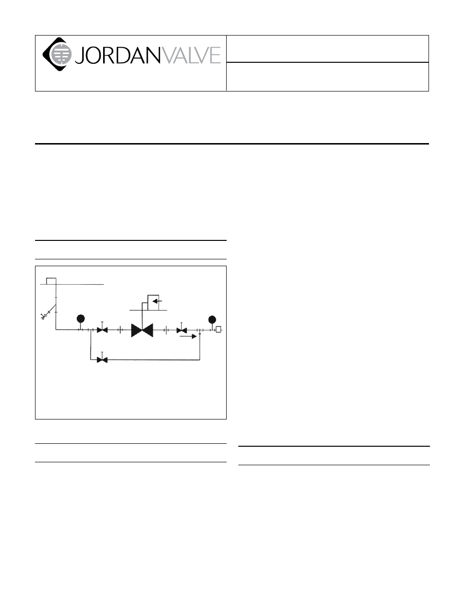
Ideal Installation
Installation
To protect the valve from grit, scale, thread chips,
1.
and other foreign matter, all pipe lines and piping
components should be blown out and thoroughly
cleaned before the valve is installed.
Shutoff valves, pressure gauges, and bypass piping
2.
should be installed as indicated in the diagram to
provide easier adjustment, operation, and testing.
In preparing threaded pipe connections, care should
3.
be exercised to prevent pipe sealing compound from
getting into the pipe lines. Pipe sealing compound
3
4
1
2
1
4
5
R
Main Line
Electric
Connection
1 Shut-off Valve
2 Pipe Union
3 Strainer & Drain Valve
4 Pressure Gauge
5 Motor Valve
6 Relief Valve
should be used sparingly, leaving the two lead threads
clean.
A line strainer should be installed on the inlet side of
4.
the regulator to protect it from grit, scale and other
foreign matter. A 0.033 perforated screen is usually
suitable. Line strainers are available for immediate
shipment from Jordan Valve.
Install the valve in the highest horizontal line of pip-
5.
ing to provide drainage for inlet and outlet piping, to
prevent water hammer and to obtain faster response.
The flow arrow on the regulator body must be
6.
pointed in the direction of flow. The valve may be
installed in any direction, but damage to the seating
surfaces may occur if installed in a vertical line with
the flow upwards.
To minimize condensation in hot vapor lines and to
7.
protect the motor from excessive heat, piping near
the valve should be insulated.
If possible, install a relief valve downstream from the
8.
regulator. Set at 15 psi above the control point of the
valve.
Expand the outlet piping at least one pipe size if the
9.
downstream pressure is 25% of the inlet pressure or
less. A standard tapered expander connected to the
outlet of the valve is recommended.
Where surges are severe, a piping accumulator is
10.
recommended.
For best control, 3’ straight sections of pipe should
11.
be installed on either side of the valve.
Wiring
Caution: Disconnect electrical power supply before
wiring motor into circuit to avoid electrical show or
possible damage to equipment. Always disconnect
power supply before attempting any wiring changes.
See the Motor Manufacturer’s literature, supplied with
the valve, for wiring connections and instructions.
2
6
Bypass Line