Jordan Valve Mark 76 Series – High Cycle, On/Off Valve User Manual
I & m mark 76, Ideal installation, Operation
3170 Wasson Road • Cincinnati, OH 45209 USA
Phone 513-533-5600 • Fax 513-871-0105
[email protected] • www.jordanvalve.com
I & M Mark 76
Installation & Maintenance Instructions for
Mark 76 On-Off Control Valves (1/4” - 2”)
Warning: Jordan Valve Control Valves must only be used, installed and repaired in accordance with these Installation
& Maintenance Instructions. Observe all applicable public and company codes and regulations. In the event of
leakage or other malfunction, call a qualified service person; continued operation may cause system failure or a
general hazard. Before servicing any valve, disconnect, shut off, or bypass all pressurized fluid. Before disassembling
a valve, be sure to release all spring tension.
Please read these instructions carefully!
Your Jordan Valve product will provide you with long,
trouble-free service if it is correctly installed and main-
tained. Spending a few minutes now reading these in-
structions can save hours of trouble and downtime later.
When making repairs, use only genuine Jordan Valve
parts, available for immediate shipment from the factory.
Jordan’s Mark 76 control valve provides straight-through
flow and Class IV shutoff for ON-OFF service. The short
stroke required to completely open or close the sliding
gate seats provides rapid response to an air signal and
prevents undue stress on the diaphragm. The wear-
resistant elastomer diaphragm has been subjected to
rigorous tests of over ten million complete cycles with no
indication of excessive wear.
Packing is of the spring-loaded chevron Teflon type to
provide long, leak-resistant service. Although the Mark
76 ON-OFF valves are economically priced, the stainless
steel seats and other internal parts are the same high
quality materials and construction used in Jordan Valve’s
Mark 70 control valves, and are completely interchange-
able with their internal parts.
Ideal Installation
Blow out pipe lines and strainers thoroughly before
1.
installation to protect the valve from grit, scale and
foreign matter. On new installations, be sure that
all thread chips are removed before inserting Mark
76.
Flow arrow on valve body must be pointed in the
2.
direction of flow. The valve may be installed verti-
cally or horizontally without affecting its operation.
Pipe sealing compound should be used sparingly,
3.
leaving the two lead threads clean. Do not use red
lead or cement for making up the joints.
Shutoff valves should be installed on the inlet and
4.
outlet side of each Mark 76 installed.
Strainers should be installed upstream of all valves
5.
to protect them from excessive dirt and scale in
pipelines (0.033 perforated screens are usually
suitable).
Operation
The valve seats are normally open (or closed) until suf-
ficient air is fed to the top of the diaphragm to overcome
the spring and close (or open) the seats. The pressure
required to operate the valve will vary according to the
pressure drop through the valve. The valve signal can be
received from a solenoid valve, a controller, or from any
other normal control source.
Trouble Shooting
If You Experience Erratic Operation:
Ruptured diaphragm: replace.
Excessive foreign matter may have lodged in the
seats: clean and replace.
Valve stroke may be out of adjustment: follow
maintenance procedures on inside pages.
Valve disc may not be moving freely in the disc
guides: follow procedures under Valve Seats on
inside pages.
Insufficient air loading pressure: increase air pres-
sure.
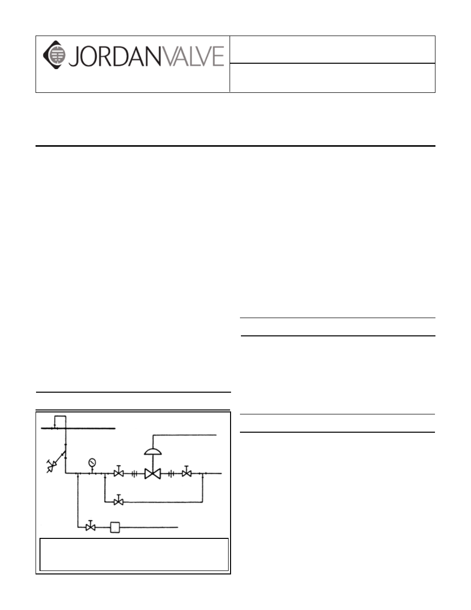
Main Line
Condensate Return
1. Shutoff Valve
4. Pressure Gauge
2. Pipe Union
5. MK76 On-Off Control Valve
3. Strainer & Drain Valve
6. Steam Trap
(on steam service)
By-Pass
Control Air
4
1
5
2
2
1
3
1
6