Jordan Valve 1051M Series Rotary Actuator User Manual
Page 2
1051M S
erieS
r
otary
a
ctuator
-2-
Actuator Mounting Continued,
Note: Refer to Table 1 for the recommended bolt
torque and tighten the cap screw as indicated.
13.
Note the valve position and direction of rotation
and position the travel indicator (Key 38)
accordingly.
14.
Position the travel indicator (Key 38) according
to the valve position noted in #13. Replace the
cover (Key 41), securing with washers
(Key 9) and cap screws (Key 8). If the holes
in the cover and housing (Key 17) do not align
properly, temporarily loosen the cap screws
(Key 32) and shift the housing slightly. Do not
stroke the actuator while the cover has
been removed.
15.
Refer to the instructions in the Adjustment
section of this manual and properly adjust the
actuator turnbuckle before proceeding
to the Loading Connection portion of installation.
Key #
Actuator Size
30
40
60
Ft•Lb N•m Ft•Lb N•m
Ft•Lb Ft•Lb
44
15
20
15
20
15
29
2 & 43
30
41
30
41
30
41
24
25
34
25
34
75
102
14
10
14
25
34
45
61
12
16
22
60
81
120
163
42
7
9
7
9
16
22
32
25
34
25
34
60
81
10
25
34
60
81
120
163
8
25
34
25
34
60
81
5
7
9
7
9
7
9
18
35
47
75
102
120
163
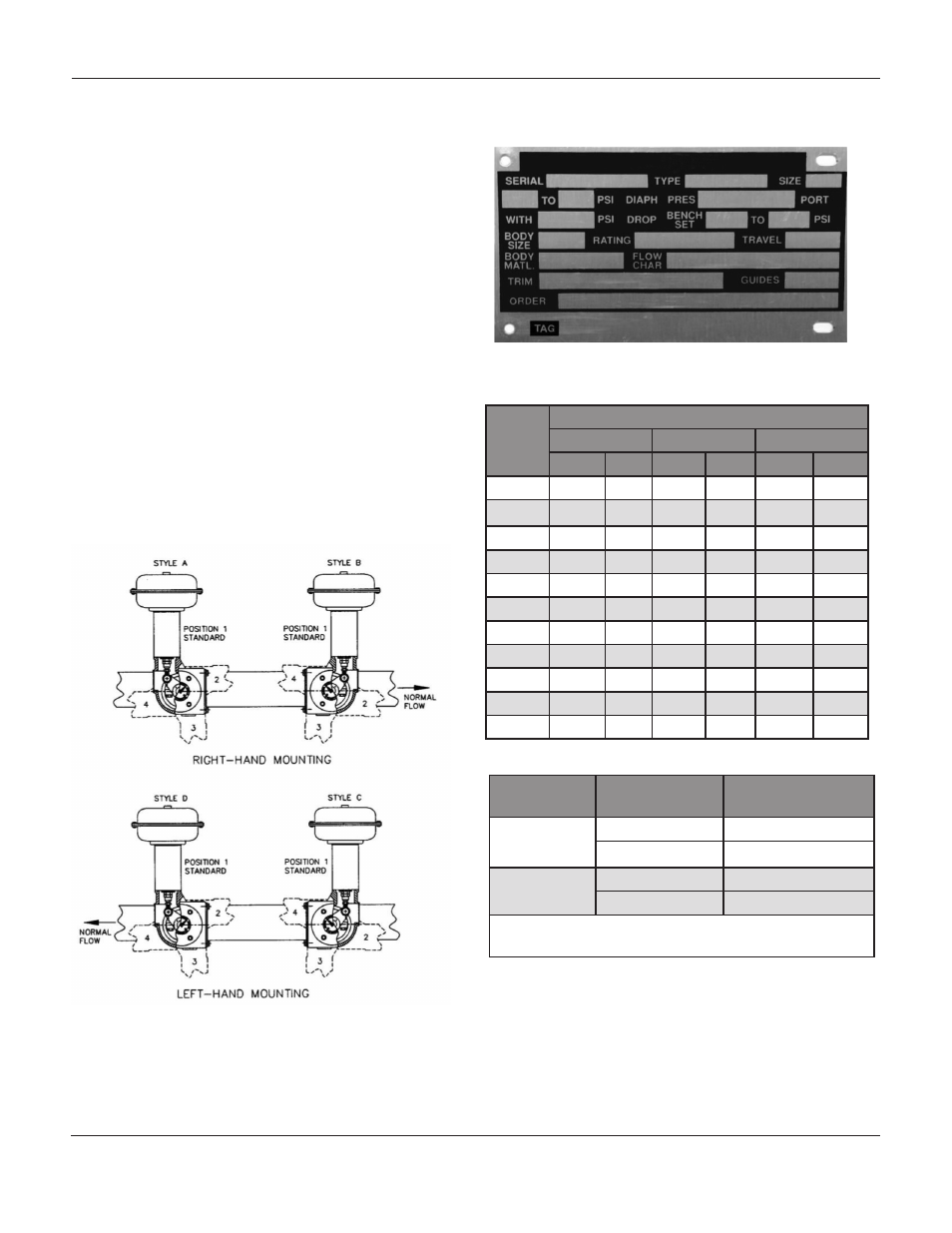
Mounting
Action
1
CVS Design V100
Valve
Right-Hand
PDTC
A
PDTO
B
Left-Hand
PDTC
C
PDTO
D
1. PDTC: Push-Down-To-Close; PDTO: Push-Down-
To-Open
Figure 2: Mounting Styles and Positions for 1051M Actuator
Table 1: Recommended Bolting Torques
Figure 1: Nameplate on 1051M Series Actuator