KACO Powador-gridsave User Manual
Page 18
Page 18
Battery unit extension - Panasonic / Sanyo for Powador-gridsave
Installation
2. Remove the fixing screws from the battery(ies) and the Battery Manage-
ment System (BMS) and remove.
3. Connect the battery(ies) with the Battery Management System (BMS) via
the relevant busbars and fasten using the fixing screws (tightening torque
of 2 Nm).
(See Figure 3 on page 17)
4. Fit covers on the Battery Management System (BMS) contacts and the
battery poles.
5. Establish communication between the top battery and the Battery Man-
agement System (BMS) using the RJ45 communication cable provided.
6. Establish communication between the batteries using the RJ45 communi-
cation cable provided.
7. Establish termination on the lowest battery using the RJ45 plug.
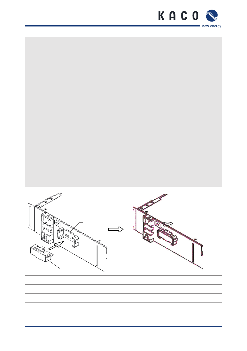
8. Following complete connection, insert the DC breaker into the DC breaker
socket on the batteries. (See Figure 4 on page 18)
9. Attaching the Plexiglass cover.
»
Battery unit successfully installed. (Complete the assembly of additional
components in line with the Powador-gridsave operating instructions)
CLICK
1
2
Figure 4: Insert service plug
Key
1
DC breaker
2
DC breaker socket