Motherboard layout, Chapter 3, Motherboard information – Lanner FW-7540 User Manual
Page 16: 5mm 180mm
11
Motherboard Information
Chapter 3
Network Application Platforms
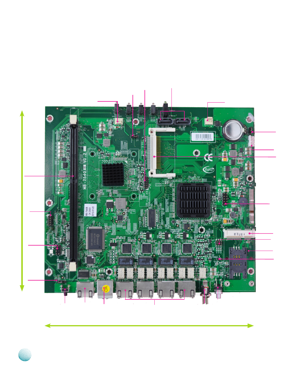
Motherboard Layout
The motherboard layout shows the connectors and
jumpers on the board. Refer to the following picture
as a reference of the pin assignments and the internal
connectors.
Ethernet Ports
(LAN2/LAN3/LAN4/LAN5)
USB2.0 Ports
(CN2)
Console Port
(LAN1)
DC-in Socket
(J3)
Mini PCI-E
Connector
(MPCIE1)
FAN2
VGA Interface
(J4)
DIMM
Socket
DIMM1
SIM Card
Connector(CON1)
SATA 1/2 Con-
nectors (J1/J2)
USB Interface
(J6)
SATA Power
Connector (J5)
Hardware/
Software
reset (JP2)
CompactFlash
Connector (CN1)
LPC I/O bus
(Port 80) (LPC1)
Clear CMOS (JP1)
Power Switch
(SW1)
208.5mm
180mm
Keyboard and
Mouse
Connectors J8)
Power Button
(CONN2)
WAN Status LED
(J9)
Reset Switch
(SW2)
FAN1
CF Master/Slave
Selector (JP3)