Chapter 3, Motherboard information – Lanner VES-270 User Manual
Page 13
13
Motherboard Information
Chapter 3
Embedded and Industrial Computing
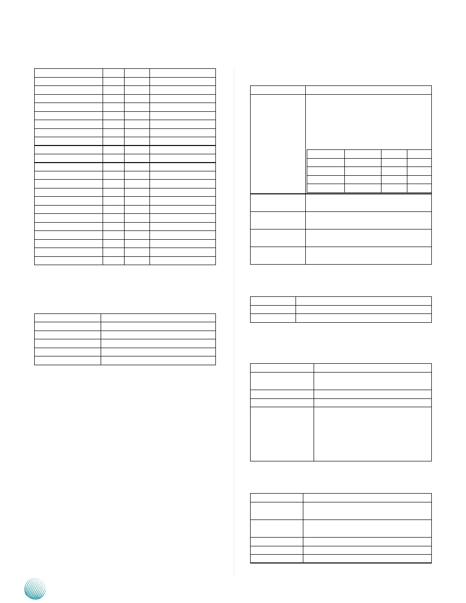
Signal
PIN
PIN
Signal
PCIE_CLK_REF--
A89 B89
VGA_RED
GND
A90 B90
GND
SPI_POWER
A91 B91
VGA_GRN
SPI_MISO
A92 B92
VGA_BLU
GPO0
A93 B93
VGA_HSYNC
SPI_CLK
A94 B94
VGA_VSYNC
SPI_MOSI
A95 B95
VGA_I2C_CK
PP_TPM
A96 B96
VGA_I2C_DAT
TYPE10#
A97 B97
SPI_CS#
NC
A98 B98
NC
NC
A99 B99
NC
GND
A100 B100
GND
NC
A101 B101
FAN_PWMOUT
NC
A102 B102
FAN_TACHIN
LID#
A103 B103
SLEEP#
VIN
A104 B104
VIN
VIN
A105 B105
VIN
VIN
A106 B106
VIN
VIN
A107 B107
VIN
VIN
A108 B108
VIN
VIN
A109 B109
VIN
GND
A110 B110
GND
Signal Description of CN1A:
Audio
•
Signal
Signal Description
AC/HDA_SYNC
HD Audio Sync
AC/HDA _RST#
HD Audio Reset
AC/HDA _SDIN[0:2] Audio CODEC Serial Data
AC/HDA _BITCLK
HD Audio Clock
AC/HDA _SDOUT
HD Audio Data
Gigabit Ethernet Signals
•
Signal
Signal Description
GBE0_MD[0:3]
+/-
Gigabit Ethernet Controller 0: Media
Dependent Interface Differential Pairs
0,1,2,3. The MDI can operate in 1000,
100 and 10 Mbit / sec modes. Some
pairs are unused in some modes, per
the following:
1000B-T
100B-T 10B-T
MDI[0]+/- B1_DA+/ TX+/- TX+/-
MDI[1]+/
B1_DB+/ RX+/- RX+/-
MDI[2]+/
B1_DC+/ X
X
MDI[3]+/
B1_DD+/ X
X
GBE0_ACT#
Gigabit Ethernet Controller 0 activity
indicator, active low.
GBE0_Link#
Gigabit Ethernet Controller 0 link indi-
cator, active low.
GBE0_Link100# Gigabit Ethernet Controller 0 100 Mbit
/sec link indicator, active low.
GBE0_Lin1000# Gigabit Ethernet Controller 0 1000
Mbit/sec link indicator, active low.
GPIO Signals
•
Signal
Signal Description
GPI[0:4]
General purpose input pins.
GPO[0:4]
General purpose output pins.
Flat Panel LVDS Signals
•
Signal
Signal Description
LVDS_BKLT_CTRL LVDS panel backlight brightness
control.
LVDS_VDD_EN
LVDS panel power enable.
LVDS_BKLT_EN
LVDS panel backlight enable.
I
2
C_DAT, I
2
C_CLK
I2C interface for panel parameter
EEPROM. This EEPROM is mounted
on the LVDS receiver. The data in the
EEPROM allows the EXT module to
automatically set the proper timing
parameters for a specific LCD panel.
LPC Signals
•
Signal
Signal Description
LPC_FRAME#
LPC frame indicates the start of an LPC
cycle
LPC_AD[0:3]
LPC multiplexed address, command
and data bus
LPC_DRQ[0:1]# LPC serial DMA request
LPC_CLK
LPC clock output - 33MHz nominal
LPC_SERIRQ
LPC serial interrupt