Connection panels – beovision 7-55, Useful hints – Bang & Olufsen BeoVision 7-40/55 Getting Started User Manual
Page 26
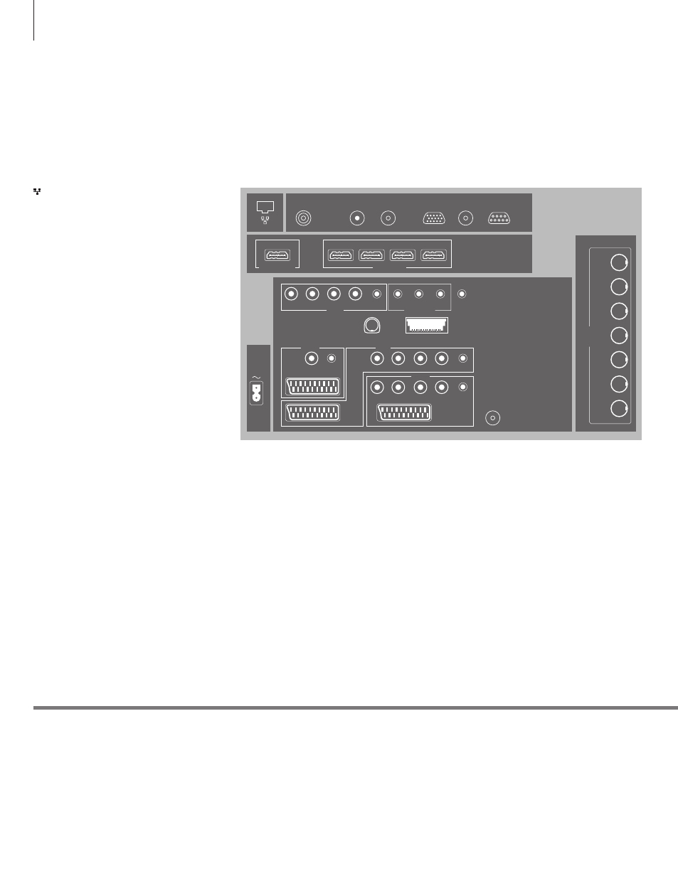
Connection panels – BeoVision 7-55
Any equipment you connect to the main connection panel must be registered in
the CONNECTIONS menu. Equipment connected to the side connection panel can
be registered in the CONNECTIONS menu.
Useful hints
Mains cord and plug Connect the ~ socket on the main connection panel of your TV to the wall
outlet. The TV is in standby mode and ready to be used.
Ethernet*
1
For connection to the Internet. For software
updates and BD-Live, if available on the Blu-ray
disc.
DVB-T/C*
2
Aerial input socket for an external aerial/cable TV
network.
DVB-S*
2
Aerial input socket for a digital satellite signal.
AERIAL OUT
Not in use.
VGA IN
Socket for connection of a High Definition video
source or a PC.
LINK TV OUT
Aerial output for distribution of video signals to
other rooms.
CINEMA CONTROL
For a Home Automation system.
HDMI OUT (PROJECTOR OUT)
Connect a projector.
HDMI IN (A–D)
For High Definition Multimedia Interface video
source or PC. An HDMI socket may be occupied
by built-in video equipment. The sources can be
registered to any of the AV socket groups. To
expand the number of HDMI sockets, connect an
HDMI Expander to the HDMI C socket.
~ – Mains supply
Connection to the mains supply.
AV1
Socket group for AV connection of a primary
recorder or set-top box. You can also connect other
types of extra video equipment.
AV2
Socket group for AV connection of additional video
equip ment.
AV3
Socket group for AV connection of additional
video equip ment.
The TV keeps a signal path open between a
recorder connected to the AV1 socket and a
recordable source connected to the AV3 socket.
This allows you to set the source on AV3 to switch
on automatically, as well as set a recorder on AV1
for timed recording of the source on AV3, provided
your connected equipment supports these functions.
AV4
Occupied by the optional Blu-ray player.
AV5
Socket group for AV connection of additional
video equip ment.
AV6
Socket group for AV connection of additional
video equip ment. You can also connect
headphones, a camera , a camcorder or a USB
device. This socket group is placed on the side
connection panel. See the illustration on page 27.
PUC (AV1 – AV3, AV5 – AV6)
For IR control signals to external equipment
connected to an AV socket.
L-IN, R-IN (AV5 – AV6)
Right and left line input. AV6 is for audio
connection of, e.g., a camera or camcorder.
1
*NOTE! Only connect to a local area network
(LAN) that does not exit your flat, house or
building.
POWER
LINK
CENTRE
1
1 (SUB)
2
3
4
5
6
MASTER LINK
STAND
AV 5
R IN
L IN
VIDEO
IN
SPDIF
PUC
SPDIF
SPDIF
PUC
Y
Y
Pb
Pb
Pr
SPDIF
Pr
AV 1
AV 3
AV 2
CONTROL
PUC
PUC
TTL
RS232
PUC 1+2
IR-IN
HDMI IN
HDMI OUT
A
PROJECTOR OUT
B
C
D
CINEMA CONTROL
VGA IN
Analogue
LINK TV
OUT
DVB-T/C
AERIAL OUT
DVB-S
26