Theory of operation, Module description – Linx Technologies HUM-xxx-RC User Manual
Page 12
– –
– –
18
19
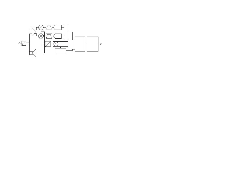
Theory of Operation
The HumRC
TM
Series transceiver is a low-cost, high-performance
synthesized FSK transceiver. Figure 28 shows the module’s block diagram.
The HumRC
TM
Series transceiver operates in the 2400 to 2483MHz
and 902 to 928MHz frequency bands. The transmitter output power is
programmable. The range varies depending on the module’s frequency
band, antenna implementation and the local RF environment.
The RF carrier is generated directly by a frequency synthesizer that includes
an on-chip VCO. The received RF signal is amplified by a low noise
amplifier (LNA) and down-converted to I/Q quadrature signals. The I/Q
signals are digitized by ADCs.
A low-power onboard communications processor performs the radio
control and management functions including Automatic Gain Control
(AGC), filtering, demodulation and packet synchronization. A control
processor performs the higher level functions and controls the serial and
hardware interfaces.
A crystal oscillator generates the reference frequency for the synthesizer
and clocks for the ADCs and the processor.
PA
LNA
0
90
FREQ
SYNTH
ADC
ADC
DEMODULATO
R
MODULATOR
ANTENNA
PROCESSOR
GPIO /
INTERFACE
INTERFACE
Figure 28: HumRC
TM
Series Transceiver RF Section Block Diagram
Module Description
The HumRC
TM
Series Remote Control module is a completely integrated RF
transceiver and processor. It has two main modes of operation: hardware
and software. Hardware operation is suitable for applications like keyfobs
where no other processor, PC or interface is present. Software operation
is more advanced and allows for more features and functionality. This
guide focuses on hardware operation with some references to software
operation. Please see Reference Guide RG-00104: the HumRC
TM
Series
Command Data Interface for details on software operation.
Since this module can act as both transmitter and receiver, terminology and
descriptions can get confusing. This guide uses the term Initiating Unit (IU)
to describe a module that is transmitting commands. Responding Unit (RU)
is used to describe a module that is receiving commands.
The module has 8 status lines numbered S0 through S7. These can be set
as inputs for buttons or contacts or as outputs to drive application circuitry.
When S0 is taken high on the IU, S0 goes high on the RU, and so forth. A
line that is an input on one side needs to be set as an output on the other
side.
Up to two of the lines S4, S5, S6 and S7 can be configured as analog
inputs through the Command Data Interface. The voltage on an analog
input can be transmitted upon activation of a digital input, or automatically
sent in response to a query from an IU. These are ideal for sensor-based
applications.
A trigger configuration provides self-timed periodic or limited-length
transmission when an input goes high.
The transceiver uses a Frequency Hopping Spread Spectrum (FHSS)
algorithm. This allows for higher output power and longer range than
narrow-band systems while still maintaining regulatory compliance. All
aspects of managing the FHSS operations are automatically handled by the
module.