Typical applications, Microstrip details – Linx Technologies RXM-GPS-FM User Manual
Page 19
– –
– –
32
33
Typical Applications
Figure 35 shows the FM Series GPS receiver in a typical application using a
passive antenna.
A microcontroller UART is connected to the receiver’s UART for passing
data and commands. A 3.3V coin cell battery is connected to the
VBACKUP line to provide power to the module’s memory when main
power is turned off.
Figure 36 shows the module using an active antenna.
A 300
Ω ferrite bead is used to put power from VOUT onto the antenna line
to power the active antenna.
NC
1
NC
2
1PPS
3
TX
4
RX
5
GND
21
NC
6
NC
7
8
NC
9
NC
10
GND 20
RFIN 19
GND 18
VOUT 17
NC 16
GND 22
NC 15
NC 14
NC 13
VCC 12
VBACKUP 11
µP
TX
RX
GND
VCC
GND
GND
VCC
GND
VCC
GND
300Ω
Ferrite Bead
RESET
NC
1
NC
2
1PPS
3
TX
4
RX
5
GND
21
NC
6
NC
7
8
NC
9
NC
10
GND 20
RFIN 19
GND 18
VOUT 17
NC 16
GND 22
NC 15
NC 14
NC 13
VCC 12
VBACKUP 11
µP
TX
RX
GND
VCC
GND
GND
VCC
GND
VCC
GND
RESET
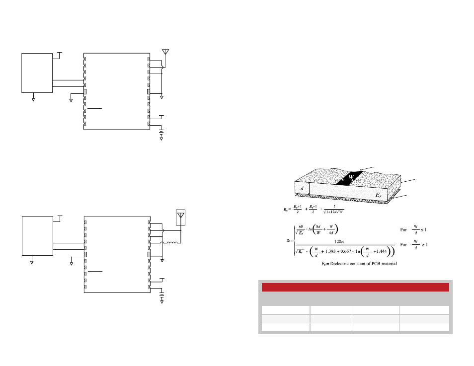
Figure 35: Circuit Using the FM Series Module with a Passive Antenna
Figure 36: Circuit Using the FM Series Module with a an Active Antenna
Trace
Board
Ground plane
Example Microstrip Calculations
Dielectric Constant
Width/Height
Ratio (W/d)
Effective Dielectric
Constant
Characteristic
Impedance (Ω)
4.80
1.8
3.59
50.0
4.00
2.0
3.07
51.0
2.55
3.0
2.12
48.0
Figure 37: Microstrip Formulas
Figure 38: Example Microstrip Calculations
Microstrip Details
A transmission line is a medium whereby RF energy is transferred from
one place to another with minimal loss. This is a critical factor, especially in
high-frequency products like Linx RF modules, because the trace leading
to the module’s antenna can effectively contribute to the length of the
antenna, changing its resonant bandwidth. In order to minimize loss and
detuning, some form of transmission line between the antenna and the
module should be used unless the antenna can be placed very close (<
1
⁄
8
in)
to the module. One common form of transmission line is a coax cable and
another is the microstrip. This term refers to a PCB trace running over a
ground plane that is designed to serve as a transmission line between the
module and the antenna. The width is based on the desired characteristic
impedance of the line, the thickness of the PCB and the dielectric constant
of the board material. For standard 0.062in thick FR-4 board material, the
trace width would be 111 mils. The correct trace width can be calculated
for other widths and materials using the information in Figure 37 and
examples are provided in Figure 38. Software for calculating microstrip lines
is also available on the Linx website.