Linx Technologies MDEV-xxx-TT User Manual
Page 11
–
–
–
–
16
17
7. The Set Module button adds the address and Permissions Mask to
the list. If a current module is selected, then the Permissions can be
updated. The Remove module button removes the selected module
from the list. The Remove All Modules button removes all of the
modules from the list.
8. The Interrupt Mask sets the conditions under which an interrupt is to
be generated on the CMD_DATA_OUT line. The Message Select menu
sets the type of message that triggers the interrupt when the Selected
Message Ready box is checked.
9. The TX Power Level Source configures how the transmitter output
power is set. It uses either the voltage on the LVL_ADJ line or the value
in the box. The accepted range of values is –20 to +12.
10. The Transmitter Mode selection sets whether the module transmits
command messages when a status line input is asserted or when it
receives a software command.
11. The Receiver Mode selection turns the receiver on or off for power
savings. If the module is set as an Initiating Unit only with all status lines
as inputs, then the receiver is disabled by default.
12. The Status Line Direction selection sets how the status lines are
configured as inputs and outputs. Either the C0 and C1 hardware lines
are used to set them in groups of 4 or the Status Line Mask is used to
set them individually.
13. The Latch Status Outputs selection configures how the latched or
momentary operation for each status line output is set. Either the
LATCH_EN hardware line is used to set all of the lines the same way or
the Latch Mask is used to set the lines individually.
14. The Custom Data box enables a custom 2-byte value to be loaded
into the module to be transmitted with each control message or
Acknowledge with Data packet.
15. The Duty Cycle configuration sets the interval and Keep on times for
automatically cycling power to the receiver.
16. The Module Identity box displays the module type, firmware version
and serial number of the active module.
17. The Read All button reads all of the current configurations from the
active module.
18. The Submit button writes all changes to the active module.
19. The Set Defaults button restores the active module to factory default
conditions.
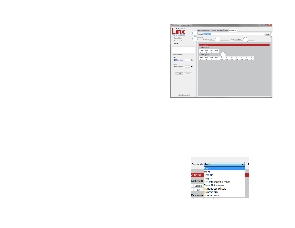
The Command Set tab (Figure 17) allows specific commands to be written
to the module.
1. The Command box shows the hexadecimal values that are written to
the module. Values can be typed into the box or a command can be
selected from the Commands menu.
2. The Response box shows the hexadecimal values that are returned
from the module in response to a command.
3. The Commands drop-down menu shows all of the commands that
are available for the active module (Figure 18). Selecting one of the
commands from this menu automatically fills in the Command box. The
values can be adjusted by typing in the box.
4
1
2
3
6
5
Figure 17: The Master Development System Software Command Set Tab
Figure 18: The Master Development System Software
Demo Command Set Tab Commands Menu