Development kit demonstration software example – Linx Technologies MDEV-xxx-TT User Manual
Page 13
–
–
–
–
20
21
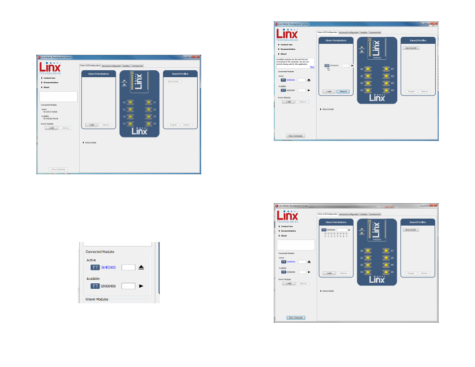
Development Kit Demonstration Software Example
This example shows how to configure two modules to work with each
other. The software defaults to the Demo & EZConfiguration tab when
opened (Figure 21).
Install Carrier Boards onto the Programming Docks and plug a USB cable
between the Programming Docks and the PC. The software automatically
detects attached devices. The first module that is identified appears
under the Active label. This is the module that is actively controlled by
the software. Subsequent modules are listed under the Available label as
shown in Figure 22.
Modules must be paired with the active device. This is accomplished by
dragging modules from the Available or Known Modules lists to the Given
Permissions window as shown in Figure 23.
Figure 21: The Master Development System Software Demo and EZConfiguration Tab
Figure 22: The Master Development System
Software Connected Modules
Once the module is dropped into the Given Permissions window it is
written to the active module’s memory. Clicking on the down arrow displays
the paired module’s Permissions Mask. This configures which output lines
the paired module is authorized to control. In Figure 24 the Permissions are
inactive since the active module only has inputs and no outputs to control.
Figure 24: The Master Development System Software Paired Modules
Figure 23: The Master Development System Software Pairing Modules