Functional description, Operating modes, Serial control interface – Linx Technologies TRM-xxx-DP1203 User Manual
Page 6
– –
– –
6
7
If the RTParam_Switch_ext bit is high, then the set is selected by the
SWITCH line. If this line is low, then Set #1 is selected. If it is high, then Set
#2 is selected.
These two sets can be used to select between transmit and receive
mode, but the TX and RX lines also need to be set appropriately. Figure 8
summarizes the XE1203F programming.
Serial Control Interface
A 3-wire bi-directional bus (SCK, SI, SO) is used to control the module. The
output signal, SO, is provided by the module and SCK and SI need to be
provided by an external microcontroller. An access Read or Write with the
XE1203 is possible only when the enable signal is active (active LOW).
For more information about the 3-wire bus refer to the XE1203 data sheet
chapter; Serial Interface Definition and Principles of Operation. Figure 9
shows a typical write sequence into a configuration register.
Functional Description
The TRM-xxx-DP1203 is a cost-effective, radio transceiver module
designed for the wireless transmission of digital information over distances
of 2 to 3 miles (3.2 to 4.8km). Regulations in the country of operation
dictate the maximum output power, so the final system range depends on
local regulations and frequency. The module is based on the XE1203F RF
transceiver from Semtech. This guide describes some of the features of
the module, but does not go into detail on the transceiver chip. For more
information, refer to the XE1203F datasheet available from the Semtech
website at www.semtech.com.
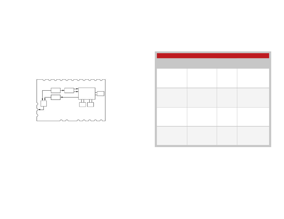
The module incorporates an antenna switch driven by two external lines
(TX and RX) and a SAW Filter placed on the receive path. Figure 7 shows a
basic block diagram of the module.
Operating Modes
When operating the DP1203, it might be useful to quickly switch between
two pre-defined operating modes, to save time and traffic on the 3-wire
serial interface bus. This may occur when the DP1203 is required to switch
quickly between receive and transmit modes, when it has to operate on
two different carrier frequencies, or when it has to switch between the high
linearity mode B and the high sensitivity mode A.
The XE1203F has five parameters that determine the operating conditions
of the transceiver. Each parameter is duplicated and saved in two sets in
the SWParam configuration register; Set #1 and Set #2. These parameter
sets can be pre-configured.
The module can quickly switch between the two sets in one of two ways
based on the RTParam_Switch_ext bit. If this bit is low then the set is
selected through the 3-wire bus using the ConfigSwitch 1-bit register. If this
bit is low, then Set #1 is selected. If it is high, then Set #2 is selected.
Figure 7: DP1203 Series Transceiver Block Diagram
SAW
LNA Match
PA Match
RF
Switch
XTAL
39MHz
XE1203F
VCO
Tank
Loop
Filter
ConfigSwitch, SWITCH Line and SWParam Configuration Register
RTParam_switch_ext
configuration
parameter
Switch Line
ConfigSwitch
Register
SWParam
configuration set
selected
0
Switch is an output:
‘1’ in TX mode
‘0’ in other modes
0
Set #1
SWParam_mode_1
SWParam_Power_1
SWParam_Rmode_1
SWParam_t_delsig_in_1
SWParam_freq_1
0
Switch is an output:
‘1’ in TX mode
‘0’ in other modes
1
Set #2
SWParam_mode_2
SWParam_Power_2
SWParam_Rmode_2
SWParam_t_delsig_in_2
SWParam_freq_2
1
0
X
Set #1
SWParam_mode_1
SWParam_Power_1
SWParam_Rmode_1
SWParam_t_delsig_in_1
SWParam_freq_1
1
1
X
Set #2
SWParam_mode_2
SWParam_Power_2
SWParam_Rmode_2
SWParam_t_delsig_in_2
SWParam_freq_2
Figure 8: ConfigSwitch, SWITCH Line and SWParam Configuration Register