Linx Technologies MDEV-GPS-R4 User Manual
Page 8
–
–
4
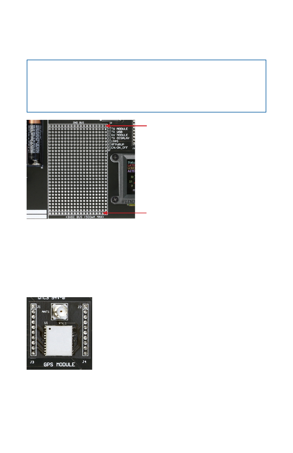
components this jumper shunt should be removed. At the bottom of the
prototyping area is a row connected to the 3V power supply and at the top
is a row connected to ground.
Note:
The on-board 3-volt regulator has approximately 300mA of
headroom available for additional circuitry. If added circuitry requires
a higher current, the user must add an additional regulator to the
prototype area or power the board from an external supply.
The GPS Receiver Section
The receiver module is mounted on a daughter board which plugs into
headers on the main development board. This daughter board has an SMA
antenna connector to allow the attachment of many different styles of GPS
antennas.
On the bottom of the main board is a CR2032 coin cell battery that
provides power to the RTC and SRAM when the receiver is powered down.
This allows the receiver to start up and obtain a position fix faster. This cell
will provide about two years of operation.
Ground Bus
+3 Volt Bus
Figure 4: The Development Board Prototyping Area
Figure 5: The Development Board GPS Receiver Section