Linx Technologies MDEV-GPS-R4 User Manual
Page 9
–
–
5
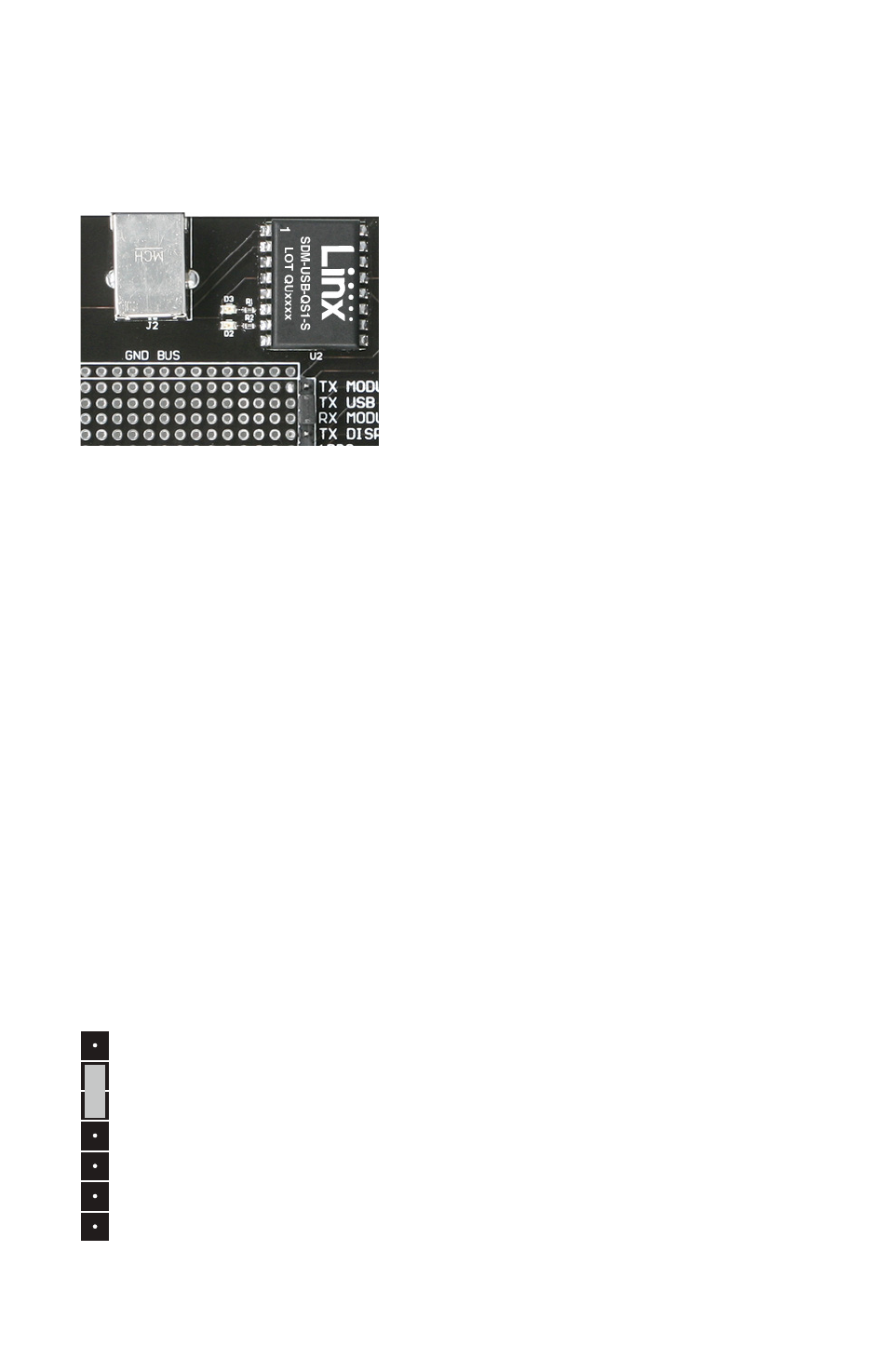
The USB Section
The development board features a Linx QS Series USB module for
interface to a PC. This allows the board to be used with the supplied
development software or with custom software developed by the user.
Drivers for the USB module are included on the software CD in the kit or
may be downloaded from www.linxtechnologies.com. Additional
information on using the QS Series USB module can also be found on the
website.
The USB connection also allows the board to be powered by the USB bus
instead of batteries. This can be convenient during development to
eliminate the need for frequent battery replacement.
Output data from the GPS module is connected directly to the USB mod-
ule, but data into the GPS module is split. This is to prevent data collisions
between the USB module and any circuitry added to the prototyping area.
To route serial data from the USB module to the serial data receive line on
the GPS module, use the supplied jumper to connect the TX USB and RX
MODULE lines on the breakout header as shown in Figure 7. Remove this
jumper for use with external circuitry. The pin marked TX DISPLAY is for
Linx use and should be left unconnected.
Figure 6: The USB Section
TX MODULE
TX USB
RX MODULE
TX DISPLAY
1PPS
RFPWRUP
EN/ON_OFF
TX MODULE
TX USB
RX MODULE
TX DISPLAY
1PPS
RFPWRUP
EN/ON_OFF
Figure 7: Jumper Configuration