Pin assignments – Linx Technologies LICAL-DEC-HS001 User Manual
Page 5
– –
– –
4
5
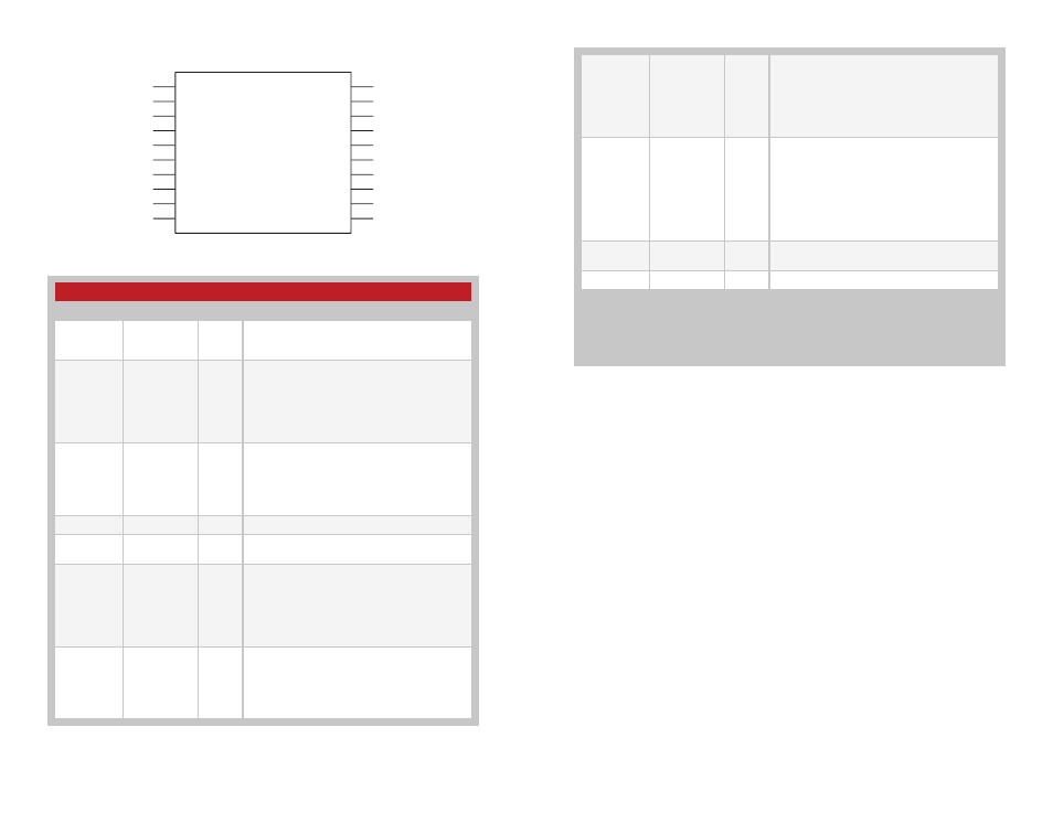
Pin Assignments
Figure 6: HS Series Decoder Pin Assignments
Pin Descriptions
Pin Number
Name
I/O
Description
1, 2, 13, 14,
17–20
D0–D7
O
Data Output Lines. These lines reproduce the
state of the encoder's data lines upon reception
of a valid packet.
3
SEL_BAUD
I
Baud Rate Selection Line. This line is used to
select the baud rate of the serial data stream.
If the line is high, the baud rate is 28,800bps,
if it is low, the baud rate is 4,800bps. The
baud rate must be set before power up. The
transcoder will not recognize any change in the
baud rate setting after it is on.
4
SEND_COPY
I
Send Copy Activation Line. When this line is
taken high while the LEARN line is high, the
decoder enters Send Copy Mode and outputs
the User Data on the KEY_OUT line. When
taken high while the CREATE_KEY line is high
at power-up, Send Copy Mode is disabled.
5, 6
GND
Ground
7
COPY_IN
I
Copy Input Line. This line is used to input the
User Data from another decoder.
8
CREATE_KEY
I
Create Key Activation Line. When this line is
taken high while the LEARN line is high, the
decoder enters Create Mode and creates a
key and encoder ID. It then sends these to
the encoder through the KEY_OUT line. When
taken high while the SEND_COPY line is high at
power-up, Send Copy Mode is disabled.
9
KEY_OUT
O
Key and Transmitter ID Output Line. When the
SEND_COPY line is high when the LEARN line
is taken high, the decoder outputs the User
Data on this line. This line also outputs the
transmitter identity upon reception of the first
valid packet of each session.
Figure 7: Pin Descriptions
D6
D7
SEL_BAUD
SEND_COPY
GND
GND
COPY_IN
CREATE_KEY
KEY_OUT
MODE_IND
D5
D4
D3
D2
VCC
VCC
D1
D0
DATA_IN
LEARN
1
2
3
4
5
6
7
8
9
10
11
12
13
14
15
16
17
18
19
20
LICAL-DEC-HS001
10
MODE_IND
O
Mode Indicator Output. This line activates
when a valid transmission is received, when the
decoder enters Learn Mode, Get Key Mode,
Create Key Mode, or Send Copy Mode, and
when the memory is cleared. This allows for the
connection of an LED to indicate to the user
that these events are taking place.
11
LEARN
I
Learn Mode Activation Line. When this line
goes high and is then pulled low, the decoder
enters Learn Mode to accept permissions from
an encoder and store it in memory. If it is held
high for ten seconds, the decoder clears all
User Data from memory. If it goes high while
the SEND_COPY or CREATE_KEY lines are
high, then the decoder enters Send Copy Mode
or Create Key Mode, respectively.
12
DATA_IN
I
Data Input Line. This line accepts the encoded
serial data stream from a receiver.
15, 16
V
CC
Supply Voltage
None of the input lines have internal pull-up or pull-down resistors. The input lines must
always be in a known state (either GND or V
CC
) at all times or the operation may not be
predictable. The designer must ensure that the input lines are never floating, either by us-
ing external resistors, by tying the lines directly to GND or V
CC
, or by use of other circuits
to control the line state.