The power supply, The encoder board – Linx Technologies MDEV-LICAL-HS User Manual
Page 6
–
–
–
–
6
7
The Power Supply
The power supply is the same on both boards and consists of a 9V battery
and a power jack connected to a 3.0V voltage regulator. The regulator
can provide approximately 500mA of current to the prototyping area. If
the added circuitry needs more than this, then the designer must add
an external supply. If the circuit consistently draws more than 100mA of
current, it might be better to use the power jack, as the battery may run
down fairly quickly, reducing testing and development time.
The jack accepts a standard 5.5mm plug with the tip ground and the outer
shell 7 to 16VDC positive supply. A reverse voltage protection diode is
included on the board to protect the circuitry in case the voltage on the
plug is reversed, but it is still a good idea to double-check the polarity.
The Encoder Board
The encoder board has three sections that are of primary interest: the
encoder area, the transmitter area, and the key exchange area.
The Encoder Area
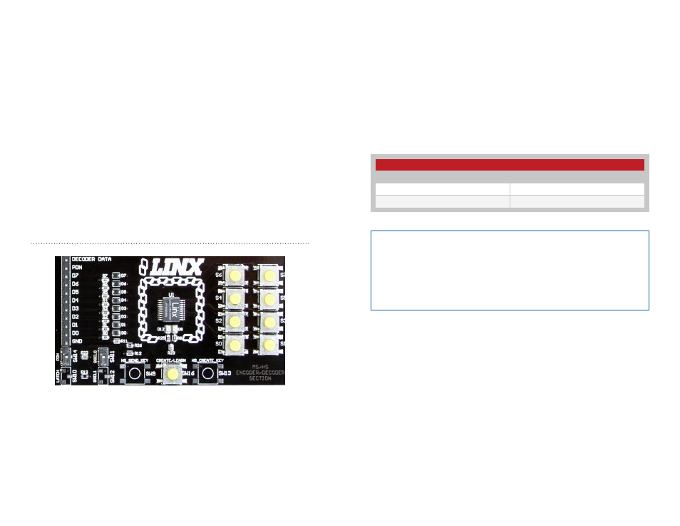
Figure 6 shows the encoder area of the development board.
The encoder is located in the center beneath the Linx logo. To the right
are buttons that pull the encoder data lines high when pressed. Button S0
corresponds to data line D0, button S1 to data line D1 and so forth.
The diodes to the left isolate the data lines from each other while allowing
any line to activate the SEND line.
Figure 6: The Encoder Area
Beneath the encoder are two LEDs. D12 is connected to the MODE_IND
line and lights up as described in the HS Encoder Data Guide. D8 is
connected to the TX_CNTL line and provides visual feedback by lighting up
when the encoder sends a word.
Beneath the LEDs is a button that is connected to the CREATE line. This
button is used to create a PIN as described in the HS Series Encoder Data
Guide.
There are two function switches to the left of the CREATE button. BSEL0 is
used to set the baud rate of the encoderr as described in Figure 7.
The PDN switch connects the TX_CNTL line of the encoder to the PDN
line of the transmitter so that the TX Control Mode of the encoder can be
tested. This mode is described in the HS Series Encoder Data Guide.
If BSEL0 is up, then the line is high (1, V
CC
); if down, then the line is low
(0, GND). If the PDN switch is up, then the encoder’s TX_CNTL line is
connected to the transmitter’s PDN line; if down, it is not connected and
the LR Series transmitter is not be activated unless the PDN line is pulled
high externally. The ES Series transmitter has an internal pull-up, so is
active unless pulled low.
Baud Rate Selection Table
SEL_BAUD0
Baud Rate (bps)
0
4,800
1
28,800
Figure 7: Baud Rate Selection Table
Note:
The decoder board must be set to the same baud rate in order
for the signal to be received correctly. The maximum baud rate for the
LR Series is 10,000bps, so only 4,800bps can be used on boards
populated with these modules. The ES Series transmitter can use both
baud rates. If the switch is up, then the line is high, if it is down, then
the line is low.