Linx Technologies MDEV-xxx-HH-CP8-MS User Manual
Page 7
–
–
–
–
8
9
Under the LEDs is a button that is connected to the LEARN line. This
button is used to learn the Code Word from the encoder as described in
the MS Series Decoder Data Guide.
There are four switches to the left of the CREATE / LEARN button. BSEL0
and BSEL1 are used to set the baud rate of the decoder as shown in
Figure 12. The Keyfob transmitter is set to 9,600bps, so BSEL0 should be
on and BSEL1 should be off. If the switch is up, then the line is high (on); if
down, then the line is low (off).
The PDN switch connects the RX_CNTL line of the encoder to the PDN line
of the receiver so that the RX Control Mode can be tested. This mode is
described in the MS Series Decoder Data Guide.
The LATCH switch places the decoder into Latch Mode when on, so that
the data lines go high when a valid signal is received and stay high until
a second valid signal is received. If the switch is off, the data lines are
momentary.
BSEL1
BSEL0
Baud Rate
0
0
2,400
0
1
9,600
1
0
19,200
1
1
28,800
Note:
The decoder board must be set to the same baud rate as the
transmitter in order for the signal to be received correctly.
Figure 12: Baud Rate Controls
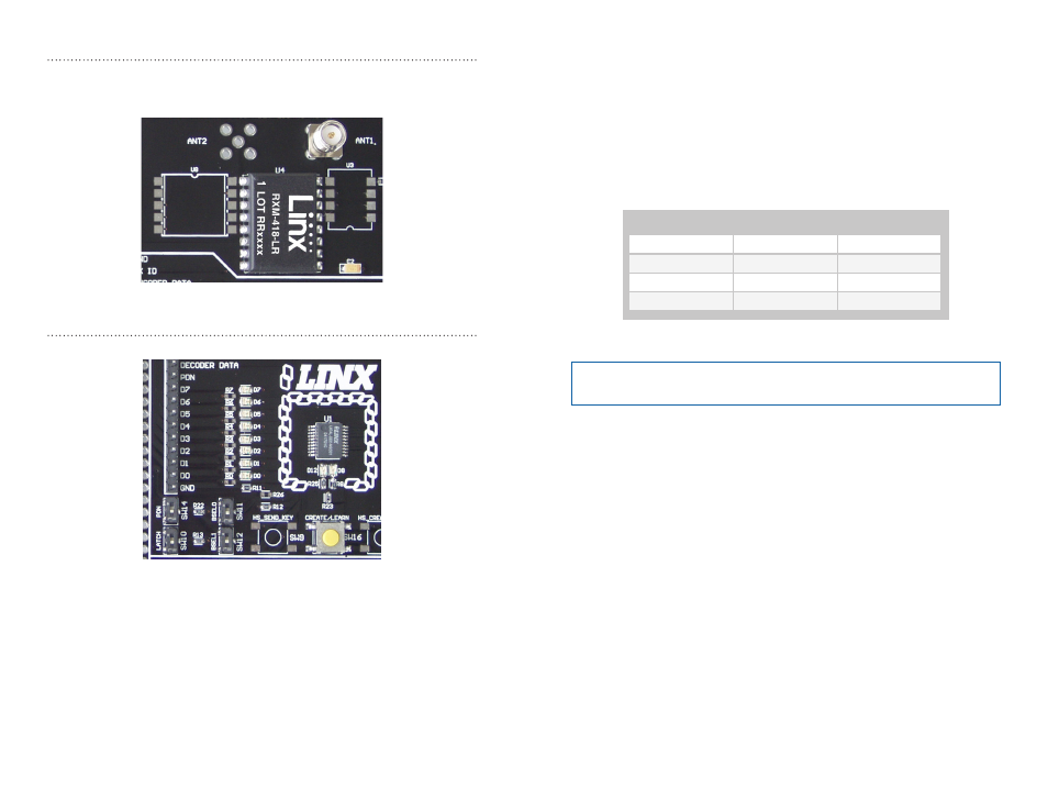
The RF Area
The Figure 10 shows the RF area of the development board. The board
uses the LR Series receiver as shown. Attach the included antenna to the
reverse polarity SMA connector before operation.
The Decoder Area
Figure 11 shows the decoder area of the development board.
The decoder is in the center beneath the Linx logo. To the left are LEDs that
are connected to the decoder data lines. These light up when the decoder
receives a signal from the transmitter instructing it to take the data line high.
LED D0 corresponds to data line D0 and so forth.
Beneath the decoder are two LEDs. D12 is connected to the MODE_IND
line. D8 is connected to the RX_CNTL line and provides visual feedback
by lighting up when the decoder activates the receiver when in RX Control
Mode.
Figure 10: The Decoder Board RF Area
Figure 11: The Decoder Area