Installing the software and drivers – Linx Technologies MDEV-xxx-HH-CP8-MS User Manual
Page 8
–
–
–
–
10
11
Installing the Software and Drivers
The Master Development System uses the QS Series USB module to
provide a simple serial interface to a PC via a USB connection. The module
requires drivers to be installed on the PC before it can function properly.
The QS Series Drivers are included on the CD with the software.
The first time the QS module is plugged into the computer, Windows
displays the Found New Hardware Wizard, which guides the installation
of the drivers. Application Note AN-00201 describes the installation of
the drivers in detail. The drivers should be installed before running the
Development Software.
The MS Master Development Software automatically starts when the CD is
inserted and the player in Figure 14 appears.
Clicking the Install Software button starts the Installation Wizard,
which guides the installation of the development software. The View
Documentation button shows a list of the application notes and manuals
related to the MS Series. Selecting one of these opens the file in Adobe
Acrobat. The Play Movie button plays a short video about Linx on the
Player Screen, which can be controlled with the Selection Keypad. Clicking
the button on the bottom right of the player opens the Linx Technologies
website in the computer’s default browser.
The View Documentation list allows for the installation of Adobe Acrobat
Reader so that the documents may be viewed. There is also the option
of installing Flash, which may be required if the Linx video does not play
correctly.
Install Software
View Documentation
Play Movie
Exit
Go to the
Linx Website
Selection Keypad
Player Screen
Figure 14: Software Installer
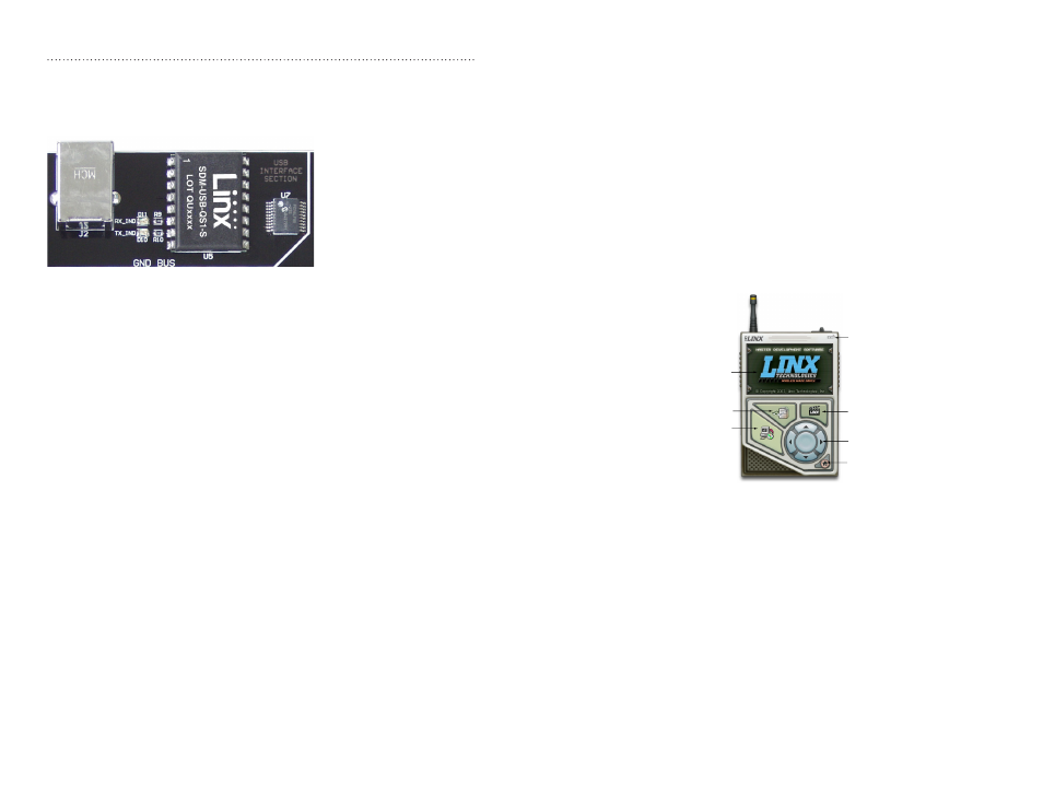
The USB Area
The decoder board has a Linx SDM-USB-QS-S USB module for use with
the included development software. This module is powered by the USB
bus, so it does not pull any current from the battery. Figure 13 shows this
section.
The microcontroller on the right monitors the data lines and generates
commands that are sent to the development software on the PC via the
QS Series USB module. The RX_IND LED to the left of the module flashes
to indicate that data is being received from the PC, and the TX_IND line
flashes to indicate that the module is sending data to the PC.
The QS Series USB module provides a simple serial link to a PC via a
USB connection. It converts logic-level serial signals to USB-compliant
signals and vice versa, so it can be connected to virtually any serial device,
including microcontrollers, RS-232 / RS-485 level converters, or Linx RF
modules. It is completely self-contained, requiring only a USB type B jack,
and includes all necessary firmware and drivers.
Figure 13: The Decoder Board USB Area