Installing the software and drivers – Linx Technologies MDEV-xxx-HH-CP8-HS User Manual
Page 10
–
–
–
–
14
15
Installing the Software and Drivers
The Master Development System uses the QS Series USB module to
provide a simple serial interface to a PC via a USB connection. The module
requires drivers to be installed on the PC before it can function properly.
The QS Series Drivers are included on the CD with the software.
The first time the QS module is plugged into the computer, Windows
displays the Found New Hardware Wizard, which guides the installation
of the drivers. Application Note AN-00201 describes the installation of
the drivers in detail. The drivers should be installed before running the
Development Software.
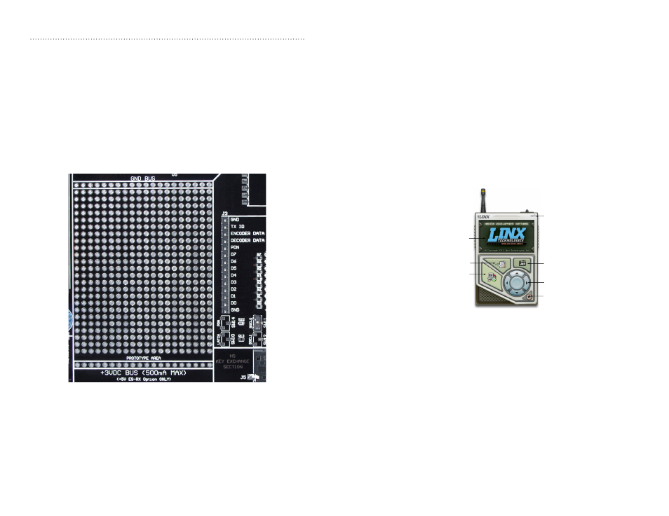
The HS Master Development Software automatically starts when the CD is
inserted and the player in Figure 16 appears.
Clicking the Install Software button starts the Installation Wizard,
which guides the installation of the development software. The View
Documentation button shows a list of the application notes and manuals
related to the HS Series. Selecting one of these opens the file in Adobe
Acrobat. The Play Movie button plays a short video about Linx on the
Player Screen, which can be controlled with the Selection Keypad. Clicking
the button on the bottom right of the player opens the Linx Technologies
website in the computer’s default browser.
The View Documentation list allows for the installation of Adobe Acrobat
Reader so that the documents may be viewed. There is also the option
of installing Flash, which may be required if the Linx video does not play
correctly.
Install Software
View Documentation
Play Movie
Exit
Go to the
Linx Website
Selection Keypad
Player Screen
Figure 16: Software Installer
The Prototyping Area
The prototyping area contains a large area of plated through holes so
that external circuitry can be placed on the board. This circuitry can be
interfaced with the HS decoder through the breakout header to the right. At
the bottom of this area is a row connected to the 3V power supply and at
the top is a row connected to ground.
All of the data lines are connected to a wire-wrap header to the right,
allowing easy access from the prototyping area. The decoder DATA_IN and
TX_ID lines are also available on the header, as well as the PDN line from
the receiver. This allows complete control of the entire system from the
prototyping area, giving the designer a great deal of flexibility in using the
boards.
Figure 15: The Prototyping Area