Fig.1, Fig.2, Operating instructions 5. maintenance – Sealey SA56 User Manual
Page 2: Preparing shears for use
4. OPERATING INSTRUCTIONS
5. MAINTENANCE
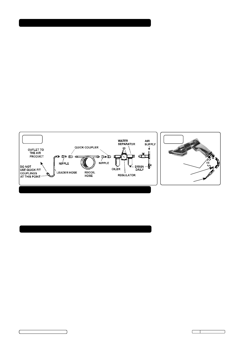
fig.1
WARNING! Ensure you read, understand and apply safety instructions before use.
4.1.
Remove the shears from the package. The tool should be assembled and ready to use.
4.2.
Connect the shears to the air hose as in section 3 fig.1 and fig.2.
4.3.
To start the shears, depress the throttle trigger.
DO NOT allow the shears to free run for extended periods as this will shorten its life.
3.1.
Air Supply
Recommended hook-up procedure is shown in fig 1.
3.1.1. Ensure tool valve (or trigger) is in the "off" position before connecting to the air supply.
3.1.2. You will require an air pressure of 90psi, and an air flow according to specification.
3.1.3.
WARNING! Ensure the air supply is clean and does not exceed 90psi while operating
the tool. Too high an air pressure and/or unclean air will shorten the product life due to
excessive wear, and may be dangerous causing damage and/or personal injury.
3.1.4. Drain the air tank daily. Water in the air line will damage the tool.
3.1.5. Clean air inlet filter weekly.
3.1.6. Line pressure should be increased to compensate for unusually long air hoses (over 8
metres). The minimum hose diameter should be 1/4” I.D. and fittings must have the same
inside dimensions.
3.1.7. Keep hose away from heat, oil and sharp edges. Check hose for wear, and make certain
that all connections are secure.
3.2. Air line couplings.
Vibration may cause failure if a quick change coupling is connected directly to the tool.
To overcome this, connect a leader hose to the tool. A quick change coupling may then
be used to connect the leader hose to the air line recoil hose. See fig.1 and fig.2.
3. PREPARING SHEARS FOR USE
WARNING! Disconnect tool from the air supply before changing accessories, servicing or
performing maintenance. Replace or repair damaged parts.
DO NOT sharpen worn blades, replace with new. Use genuine parts only. Unauthorised
parts may be dangerous and will invalidate the warranty.
Note: Numbers in brackets refer to item numbers in the parts diagram.
5.1
Before replacing blades, note carefully the orientation of cutting blade edges. It is possible
to fit the blades incorrectly.
On removal be aware of the two spacers, one between outer
blades and one at the pivot point of the central blade, these are critical to the tool (fig.3).
5.2.
To replace the blades (34, 35 and 37), unscrew the three socket head cap screws (32) and
slide the cutter housing (31) off the clamp nut (27). Remove the three socket head cap
screws (32) that secure the blades (34, 35 and 37) and remove the blades. Fit new blades,
ensuring the spacers (36) are correctly positioned and refit the socket head cap screws.
Smear silicone grease or similar on to the outer race of the ball journal fig.4 and slide the
cutter housing onto the eccentric mechanism housing, tighten the cap screw nearest
the trigger. Tighten the other two socket head cap screws, the spacers ensure the blades
will not be clamped.
Original Language Version
SA56 Issue: 1 - 10/05/13
fig.2
Quick coupler
Male hosetail
adaptor
Leader hose
© Jack Sealey Limited 2013