Sealey MK67 User Manual
Mk67.v2, Masking paper dispenser, Instructions for
INSTRUCTIONS FOR:
Masking PaPer DisPenser
MODEL:
Mk67.V2
Thank you for purchasing a Sealey Product. Manufactured to a high standard this product will, if used according to these instructions and properly
maintained, give you years of trouble free performance.
IMPORTANT: PLease reaD THese insTrUCTiOns CareFULLY. nOTe THe saFe OPeraTiOnaL reQUireMenTs, Warnings anD CaUTiOns.
Use THis PrODUCT COrreCTLY anD WiTH Care FOr THe PUrPOse FOr WHiCH iT is inTenDeD. FaiLUre TO DO sO MaY CaUse DaMage
Or PersOnaL inJUrY anD WiLL inVaLiDaTe THe WarranTY. PLease keeP insTrUCTiOns saFe FOr FUTUre Use.
MK67.V2
Issue No: 1 - 26/08/08
Ensure the dispenser is on a reasonably flat, level floor before loading.
Be aware that the paper cutting blades are sharp, handle with care.
DO nOT use the dispenser for any purpose other than that for which it is designed.
1. saFeTY insTrUCTiOns
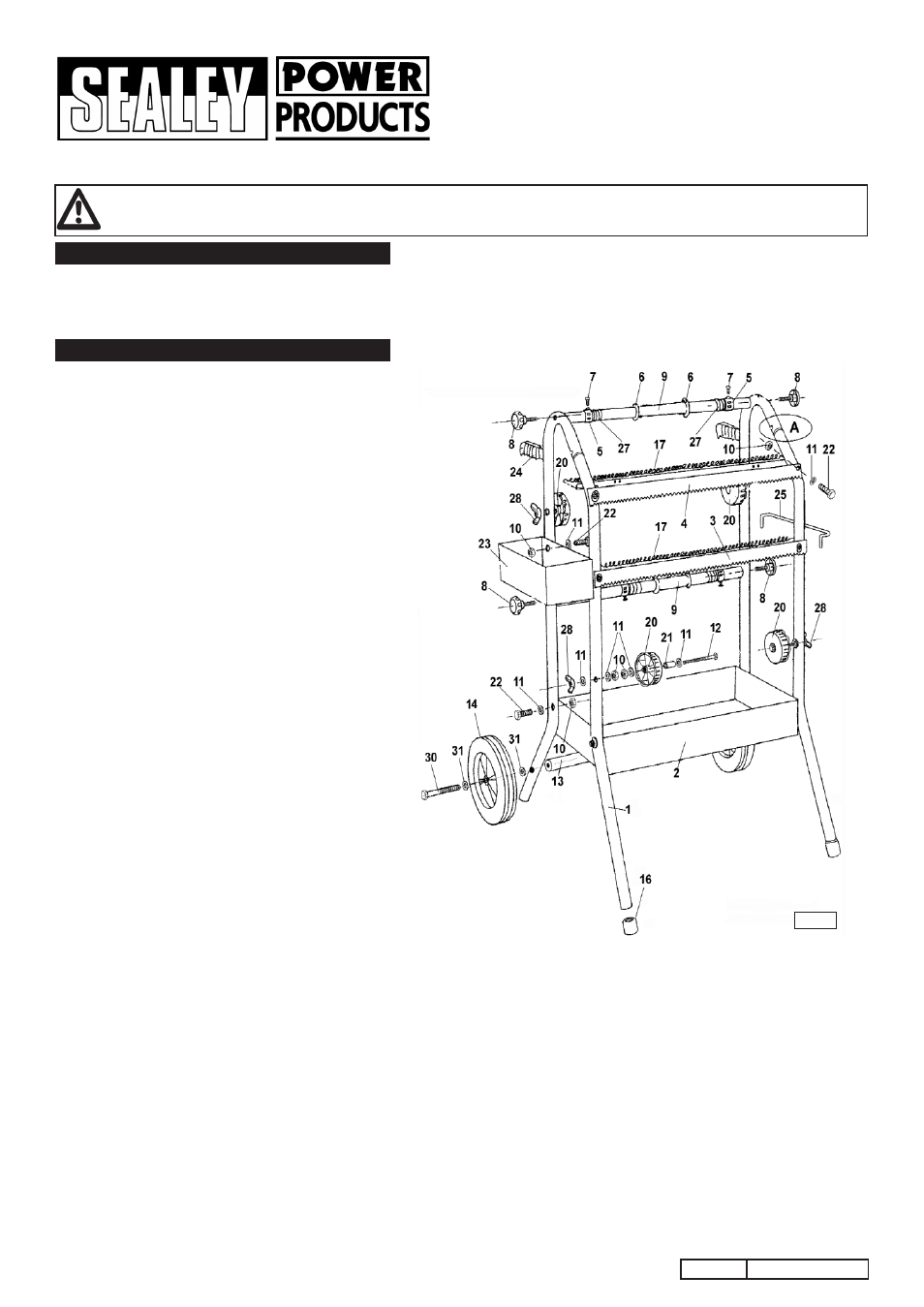
2. asseMBLY
iTeM ParT nO. DesCriPTiOn
1A&B MK66/01
FRAME
2
MK67/02
TRAY
3
MK67/03
BOTTOM PAPER BLADE
4
MK67/04
TOP PAPER BLADE
5
MK66/05
PAPER RETAINER
6
MK66/06
PAPER WASHER
7
MK66/07
SCREW
8
MK66/08
KNOB
9
MK67/09
PAPER BAR
10
MK66/10
NUT
11
MK66/11
WASHER
12
MK66/12
BOLT
13
MK67/13-B AXLE
14
MK67.V2-14 WHEEL
iTeM ParT nO. DesCriPTiOn
16
MK66/16
TIP FOOT
17
MK67/17
PAPER SPRING
20
MK66/20
TAPE REEL
21
MK66/21
HUB
22
MK66/22
BOLT
23
MK66/23
TOP TRAY
24
MK66/24
HANDLE GRIP
25
MK66/25
HANGER
27
MK66/27
RETAINING SPRING
28
MK66/28
KNOB OR WING NUTS
29
MK66/FK FIXING KIT(not shown)
30
MK67/15-B BOLT
31
MK67/29
WASHER
2.1 To assemble the side frames compress the silver
latch button at the top of the front leg
1B and insert
the tube into the back leg tube
1a until they snap
together. (See A in Fig.1).
2.2 Onto each end of the two paper bars 9 slide a large
retaining washer
6 followed by a retaining spring 27
followed by a black plastic retaining ring
5. Insert a
screw
7 into the threaded block on each retaining
ring.
2.3 Attach the side frames to each end of the paper bars
as shown in Fig.1 using the four black knobs
8.
2.4 Fit the bottom tray between the side frames and bolt
it to each leg using a bolt
22, a washer 11 and a nut
10.
2.5 Attach the upper paper blade 4 to the front of the
frame using two bolts
22, two washers 11 and two
nuts
10. (The upper blade has a wider profile than the
lower blade).
2.6 Attach the lower paper cutter 3 to the front of the
frame using two bolts
22, two washers 11 and two
nuts
10.
2.7 Attach a paper spring 17 to the back edge of each
paper cutter. Hook one end of the spring to the
notched back corner of the metalwork and stretch it
across and hook it to the other back corner. Take
care to avoid the paper cutter teeth when doing this.
2.8 To assemble the four tape reels as shown in fig.1
take a long bolt
12 and drop a washer 11 onto it
followed by a black plastic hub
21. Slide a reel 20
over the bolt and onto the hub ensuring that it is the
right way round. Retain the assembly using another
washer followed by a nut. After the nut has been
tightened the reel should still run freely on the hub.
Attach another nut to the bolt and insert the bolt
through the frame in one of the four places indicated
in Fig.1. Retain the assembly in place using a wing
nut
28 and a washer 11.
2.9 Attach the top tray 23 to the side of one of the frames
using two bolts
22, two washers 11 and two nuts 10.
The nuts and washers should be on the inside of the
tray.
2.10 Attach the hanger 25 to the side of the opposite
frame at the same level as the top tray. Insert the
ends of the hanger into the holes in the side of the
frame and tip the hanger forwards so that the first
bend in either end of the hanger is inside each frame
tube.
2.11 The dispenser has a tubular axle which allows an
axle bolt to be screwed into either end and also fixes
the axle to the frame. Slide a washer
31 over a bolt
30 followed by a wheel 14 and another washer 31.
Position the tubular axle
13 between the two rear
legs and pass the axle bolt through the rear leg and
screw it into the thread in the end of the axle. Attach
the other wheel in the same way. Tighten the axle
bolts until the wheel is lightly gripped then back off
slightly to allow the wheels to rotate.
Fig.1