Sealey HSPT05 User Manual
Hspt05, Heating system pressure tester, Introduction
HEATING SYSTEM PRESSURE TESTER
I N S T R U C T I O N S F O R M O D E L :
HSPT05
Thank you for purchasing a Sealey product. Manufactured to a high standard this product will, if used according to these instructions
and properly maintained, give you years of trouble free performance.
IMPORTANT: PLEASE READ THESE INSTRUCTIONS CAREFULLY. NOTE THE SAFE OPERATIONAL REQUIREMENTS, WARNINGS & CAUTIONS. USE
THE PRODUCT CORRECTLY AND WITH CARE FOR THE PURPOSE FOR WHICH IT IS INTENDED. FAILURE TO DO SO MAY CAUSE DAMAGE AND/OR
PERSONAL INJURY AND WILL INVALIDATE THE WARRANTY. PLEASE KEEP INSTRUCTIONS SAFE FOR FUTURE USE.
2. INTRODUCTION
The HSPT05 is primarily intended for the pressure testing of new domestic heating installations prior to the connection of the boiler and also to fault-find leakage and air
ingress problems on existing systems. When correctly connected to a pipe/radiator network or complete central heating system the hydraulic, hand operated unit is used
to build up to a required testing pressure. The unit features a built-in water filter to prevent debris entering the system being tested. The handle has a soft grip for
comfort and control. There is a guard around the gauge to prevent it from damage and a pump locking key.
p
WARNING! DO NOT exceed the recommended testing pressure for any water heating system or any component within that system.
7
DO NOT use this pressure tester for tasks it was not designed to perform.
7
DO NOT use equipment if damaged.
3
Establish the correct testing pressure for the pipework/installation to be tested by referring to the system specification and/or the manufacturers recommendations.
3
Maintain the equipment in good and clean condition for best and safest performance.
3
Wear approved eye protection. A full range of personal safety equipment is available from your Sealey dealer.
3
Wear suitable clothing.
3
When not in use store in a safe, dry, childproof area.
3
Systems that have been sealed off or modified for testing must be returned to their original state before the heating system can be used again.
1. SAFETY INSTRUCTIONS
HSPT05 - 1 - 241104
NOTE: It is our policy to continually improve products and as such we reserve the right to alter data, specifications and component parts without prior notice.
IMPORTANT: No liability is accepted for incorrect use of product.
WARRANTY: Guarantee is 12 months from purchase date, proof of which will be required for any claim.
INFORMATION: For a copy of our latest catalogue and promotions call us on 01284 757525 and leave your full name and address, including postcode.
01284 757500
01284 703534
Sole UK Distributor
Sealey Group,
Bury St. Edmunds, Suffolk.
www.sealey.co.uk
Web
3. OPERATING INSTRUCTIONS
3.1 If you are not a trained plumber you must seek professional guidance from an approved plumber on the correct use of this product.
3.2 Establish the correct testing pressure for the pipework/installation to be tested by referring to the system specification and/or the manufacturers recommendations.
3.3 Any existing installations must be pressure tested in the OFF condition.
3.4 Any system to be tested must be temporarily sealed off in order for the test pressure to build up. When pressure testing is finished the system tested must be returned
to its original design state before it can be used again.
3.5 If the system contains pressure relief valves these must be temporarily disabled if the system is to be tested over 3bar. After testing is complete the pressure relief
valves must be reactivated.
3.6 The system to be tested must be fully water filled in order for the water pressure to build up.
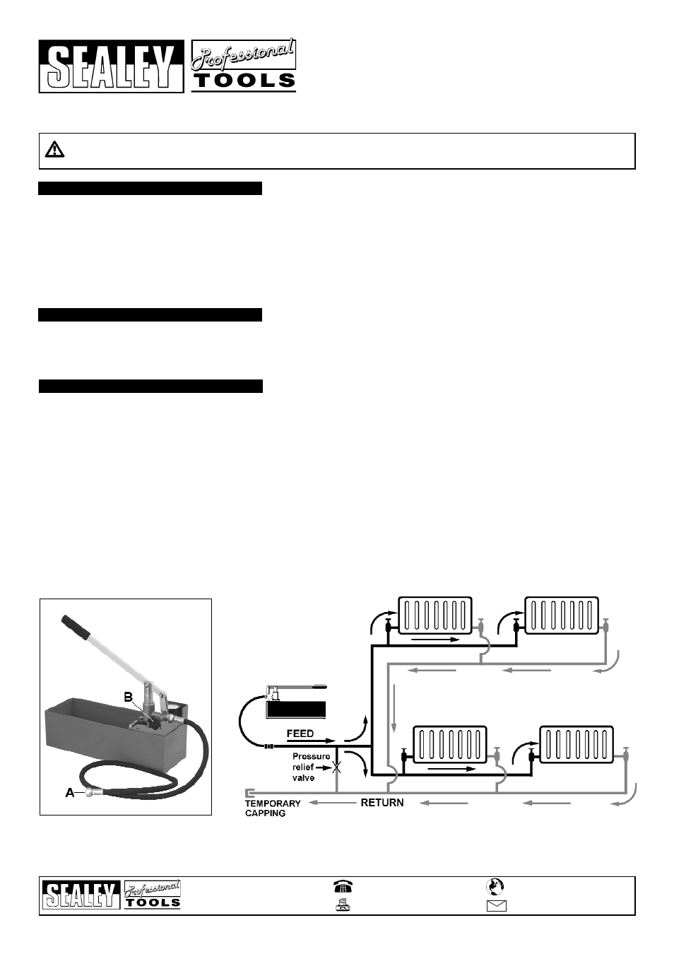
3.7 Attach the flexible hose to the pump outlet.
3.8 Locate a suitable point on the system for connection and attach the other end of the hose to it. If necessary use an adaptor suitable for the female 1/2 inch BSP
hose connection (A).
3.9 Unlock the pumping handle by holding it horizontal and sliding the locking bar out from beneath the pivot point.
3.10 Fill the reservoir with water and close the valve (B).
3.11 Commence pumping until the gauge registers the required pressure.
3.12 Leave the system pressurised for a period of time and observe the gauge.
If the pressure drops there is a leak in the system and a visual inspection should be made.
3.13 When testing is finished open valve (B) to release the pressure and allow water to flow back into the reservoir.
3.14 Disconnect the tester from the system and reseal the point of connection.
3.15 Where a system has been temporarily sealed for testing ensure that the system is returned to its original condition.