Sm1306, Fig.3 fig.4 fig.5, Adjustments – Sealey SM1305 User Manual
Page 3
4.4.
Upper blade guide position
4.4.1. The upper blade guide should always be adjusted to about 3mm above the workpiece. To adjust, loosen the locking knob
(fig.1.C) and lower the assembly to the required position. Tighten locking knob.
4.5.
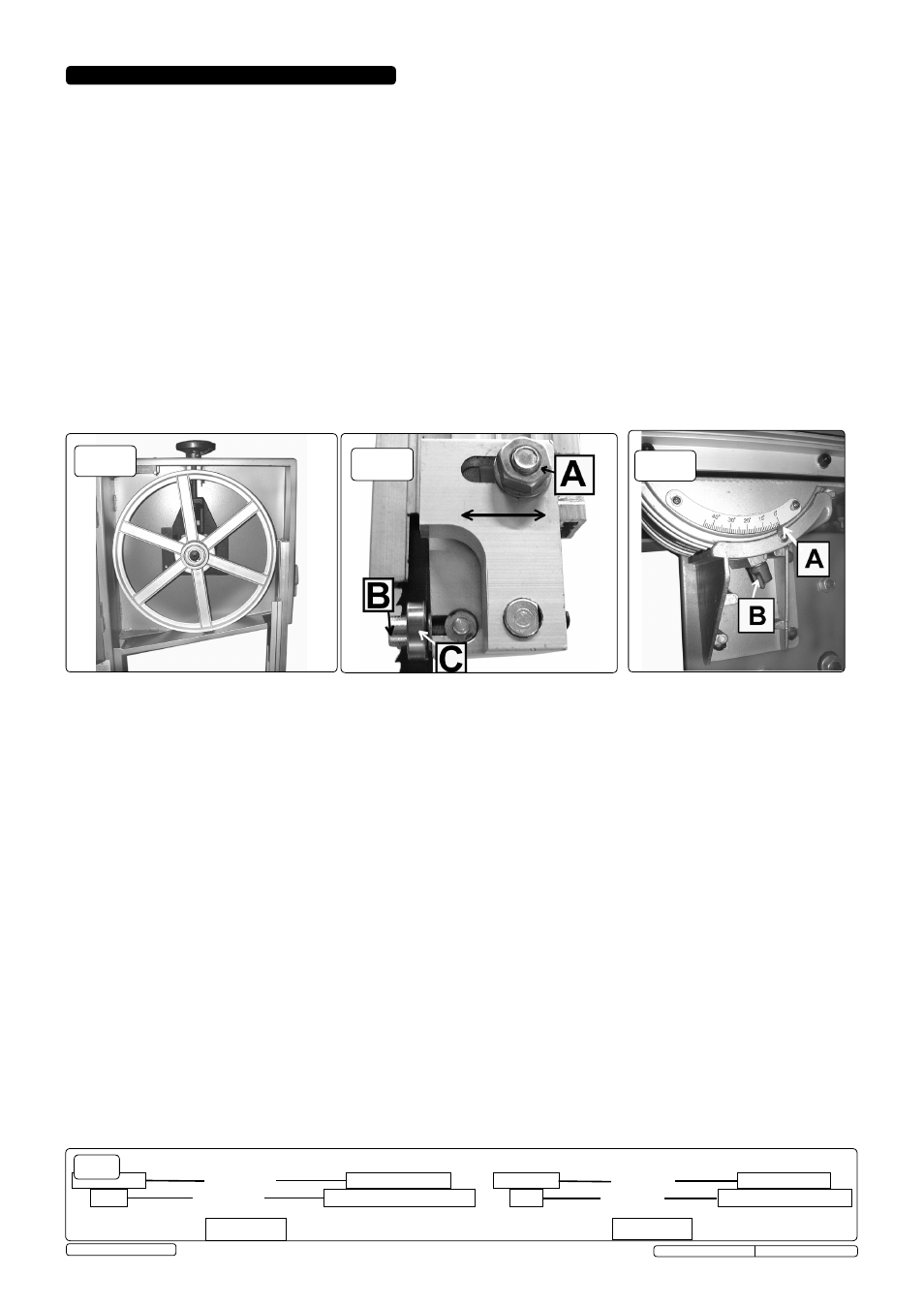
Upper blade guide bearing adjustment
4.5.1. The upper blade guide support bearing prevents the saw blade from being pushed too far back when cutting. It should be adjusted
to 0.75mm behind the blade. Loosen nut (fig.4.A) and by sliding the bearing holder left or right, position the bearing correctly and then
tighten the nut to secure. Re-check for correct positioning.
4.5.2. The upper blade guide side bearings prevent the saw blade from being pushed sideways when cutting. Adjust the bearings (fig.4.C) so
that each is just clear of the blade. Loosen the allen bolts (fig.4.B) and slide the bearings to position them correctly. Tighten allen bolt
to secure. Re-check for correct positioning.
4.6.
Lower blade guide bearing adjustment
4.6.1. The three lower guide bearings should be adjusted using the same procedure as for the upper guide bearings above. They are
positioned within the lower blade cover.
4.6.2. All three bearings are held in place by allen bolts. Position each bearing correctly and re-check for correct positioning after tightening
the allen bolts.
Notes: a) Always check and adjust both upper and lower guides at the same time.
b) Carry out these checks/adjustments every time the blade is changed.
c) The blade will be damaged if the teeth contact the guides/guide bearings.
4.7.
Drive belt tension
4.7.1. Open lower blade cover and check belt tension. Belt should have approx. 5mm mid-span deflection under finger pressure.
4.7.2. To adjust belt tension turn drive belt tensioner knob (fig.1.K) until correct tension is achieved. Close and lock cover.
4.8.
blade speed
4.8.1. Open lower blade cover and remove all belt tension by turning belt tensioner knob anticlockwise (fig.1.K).
4.8.2. Move belt to the required pair of pulleys (see fig.6. for required blade speeds).
4.8.3. Tension belt correctly (see 4.7.) by turning drive belt tensioner knob (fig.1.K) and close and lock cover.
4.9.
mitre gauge
4.9.1. The mitre gauge (fig.1.I), which can be located in either of the two table slots, is adjustable through 45O in either direction. Loosen the
central locking knob, adjust and then tighten locking knob.
4.10. Table Angle
4.10.1. Loosen the knob (fig.5.A) and adjust table to required angle using the scale (fig.5.B) as a guide. Tighten knob when in required
position.
motor Pulleys
blade Wheel Pulleys
660m/min.
540m/min.
Sm1306
motor Pulleys
blade Wheel Pulleys
660m/min.
360m/min.
Sm1305
fig.6
WARNING! ENSURE THAT THE bANDSAW IS DISCONNECTED FROm THE POWER SUPPLY bEFORE ATTEmPTING ANY
ADJUSTmENTS.
4.1.
Changing the blade
4.1.1. Turn the blade cover locks (fig.1.B) anticlockwise to open the upper and lower covers.
4.1.2. Turn blade tension adjustment knob anticlockwise (fig.1.A) to slacken the blade.
4.1.3. Remove the table side guide and the securing bolt from the table blade slot.
4.1.4. Carefully remove the blade.
4.1.5. Install the new blade. Be sure the teeth are pointing downwards and outwards. Refit securing bolt and table side guide.
4.1.6. Adjust new blade to the correct tension (see 4.2.) and check, and adjust if necessary, tracking (see 4.3.) and blade guide adjustment
(see 4.5.).
4.1.7. Close both blade covers and lock with blade cover locks.
4.2.
Adjusting blade tension
4.2.1. Open the blade covers and check to ensure that blade is centred on both wheel rims (if not, see section 4.3).
4.2.2. Turn the blade tension knob (fig.1.A) to adjust the blade tension - clockwise to tighten, anticlockwise to slacken.
Correct tension is reached when the blade gives slightly to firm finger pressure at mid-span. Do not over-tighten.
4.2.3. Close both blade covers and lock with blade cover locks.
4.3.
Adjusting blade tracking
4.3.1. Open blade covers and carefully rotate the upper blade wheel (fig.3) clockwise by hand, to determine whether blade is tracking
correctly - blade should be on the centre of each wheel rim.
4.3.2. If adjustment is needed, turn the tracking knob (fig.2.M) whilst continuing to turn the upper blade wheel. Note the effect on
the tracking and continue to turn tracking knob until tracking is correct.
4.3.3. Close both blade covers and lock with blade cover locks.
4. ADJUSTmENTS
fig.3
fig.4
fig.5
Original Language Version
SM1305, SM1306 Issue:3 (SP) - 04/12/13
© Jack Sealey Limited