Fig.6 fig.5 fig.2 fig.4, Fig.3, Operating instructions – Sealey SJBEX200LP User Manual
Page 2
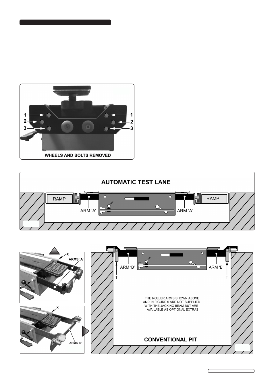
4. oPERAtING INStRuCtIoNS
note: to assist in matching different runner height arrangements
the wheels on the arms can be mounted in one of 3 positions
as shown in the diagram below.
4.2.
Locating jacking beam in a conventional inspection pit.
NOTE: The roller arms shown in figures 5 & 6 are not supplied with
the unit but are available as optional extras.
4.2.1 Fit the optional roller arms (see 'B' in fig.5).
4.2.2 extend the roller arms (B) to the correct width for the
inspection pit runners. See figs.5 and 6 below.
4.2.3 lower the jacking beam into the pit and locate the rollers onto
the runners. With the beam central in the pit lock the arms
in position by tightening the two locking bolts 'X' seen in
fig.5 below.
4.2.4 Adjust the spring tension screw on all four rollers (see 't' in
fig.6) so that the rollers will just support the weight of the
jacking beam on its own and allow it to travel freely over the
pit. When the jacking beam is in use the weight of the vehicle
will overcome the spring tension, pushing the jacking beam
downwards until the roller arms themselves make contact
with the sides of the pit.
4.3.
to jack a vehicle.
Make sure the vehicle hand brake is on and automatic
vehicles are in 'park' before attempting to raise the vehicle.
4.3.1 With the beam in the lowered position, roll it under the
vehicle to the position where the lift is required.
note: ensure you use the vehicle manufacturer’s designated
jacking points.
4.3.2 the majority of lift applications require the use of two
saddles.
4.3.3 evaluate which height extension posts may be required.
fig.6
fig.5
fig.2
fig.4
WARNING! this jacking beam weighs 97kg. Seek assistance
before attempting to locate jacking beam on inspection pit
runners and Automatic test Lanes.
4.1.
Locating jacking beam in an AtL (Automatic test Lane).
4.1.1 extend the roller arms (A) to the correct width for the pit lift
runners. See figs.3 and 4 below.
4.1.2 lower the jacking beam into the pit and locate the rollers into
the lift runners. With the beam central in the pit lock the arms
in position by tightening the two locking bolts 'X' seen in fig.4
below.
fig.3
Original Language Version
sJBeX200lP Issue: 3 - 16/10/09