Sealey SM3002DFD User Manual
Sm3002dfd, Digitalfeed displayfor sm3002, Model
DIGITALFEED DISPLAYFOR SM3002
MODEL:
SM3002DFD
Thank you for purchasing a Sealey product. Manufactured to a high standard this product will, if used according to these instructions
and properly maintained, give you years of trouble free performance.
IMPORTANT: PLEASE READ THESE INSTRUCTIONS CAREFULLY. NOTE THE SAFE OPERATIONAL REQUIREMENTS, WARNINGS & CAUTIONS.
USE THE PRODUCT CORRECTLY AND WITH CARE FOR THE PURPOSE FOR WHICH IT IS INTENDED. FAILURE TO DO SO MAY CAUSE DAMAGE
AND/OR PERSONAL INJURY AND WILL INVALIDATE THE WARRANTY. PLEASE KEEP INSTRUCTIONS SAFE FOR FUTURE USE.
INSTRUCTIONS FOR:
1.
INTRODUCTION
Digital display for the cross slide and the compound tool rest to replace the standard graduated scales. These LCD units improve accuracy, save
reading time and minimise errors. Imperial or Metric readings may be selected and the reading can be zeroed at any point. Three decimal place
(Metric) and four decimal place (Imperial) displays with an accuracy of ± 0.025mm/0.001.
2.
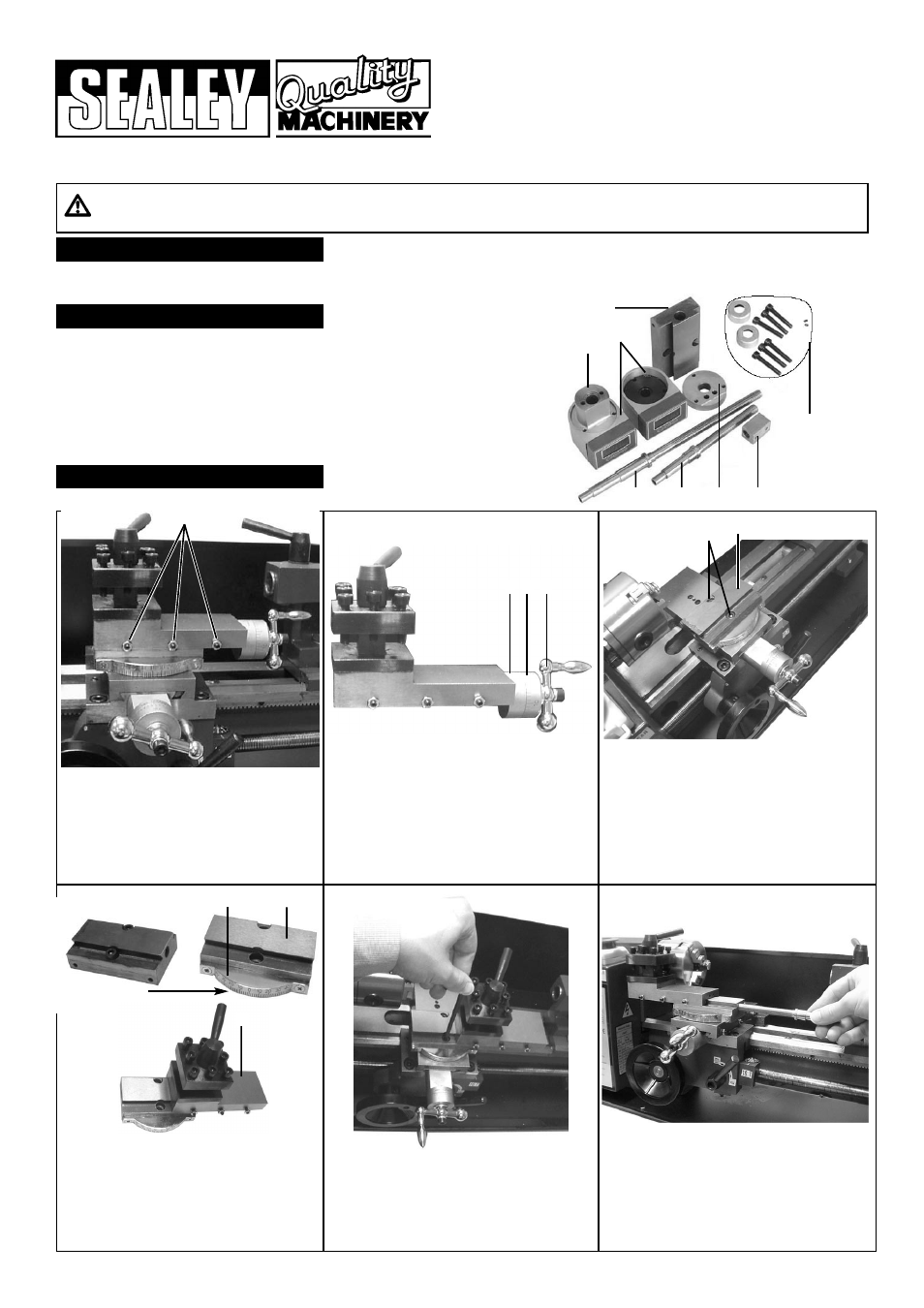
CONTENTS
3.
INSTALLATION 1
3.1 Loosen the compound rest gibs
(fig 1a) and crank the compound rest
feed handle anticlockwise to remove the
top of the compound rest from the
compound rest bottom.
3.2 Undo the handle screw of the graduated
scale (fig 2a) and remove the spring clip
and scale (fig 2b). Remove the compound
rest screw retainer (fig 2c) (retaining the
fixing screws for future use) and remove
the compound rest feed screw.
3.3 Remove the two large hex screws
(fig 3a) (retaining them for future use).
Remove the compound rest
bottom (fig 3b) from the cross slide.
3.4 Move the protractor (fig 4a) to the
new compound rest bottom (fig 4b) and
slide the compound rest top (fig 4c) a
short way onto the new compound rest
bottom, being sure to leave the two
large screw holes uncovered.
3.5 Screw the compound rest back onto
the cross slide using the two large hex
screws. Adjust the gib screws so that the
compound rest may be moved by hand
but with some resistance.
3.6 Screw the new compound rest feed
screw into the compound rest bottom.
Installing the Compound Rest digital display.
1. Cross slide feed screw
2. Compound rest feed screw
3. Screws and spacers
4. Cross slide screw retainer
5. Cross slide feed nut
6. Compound rest screw retainer
7. Compound rest bottom
8. Digital displays
1
2
6
5
4
7
8
3
fig 1
fig 2
fig 3
fig 4
fig 5
fig 6
a
c b a
a b
a
b
c
SM3002DFD - 1 - 100504