Fig. 3, Set- up and operation – Sealey SM2502 User Manual
Page 4
WARNINg! Before operating the drilling/milling machine ensure you are wearing
approved safety goggles and gloves to protect you from swarf and metal particles. If using
cutting oil or coolant a face mask may be necessary to avoid breathing any vapour
generated. Ensure that all other safety instructions in section 1 are followed carefully.
4.0
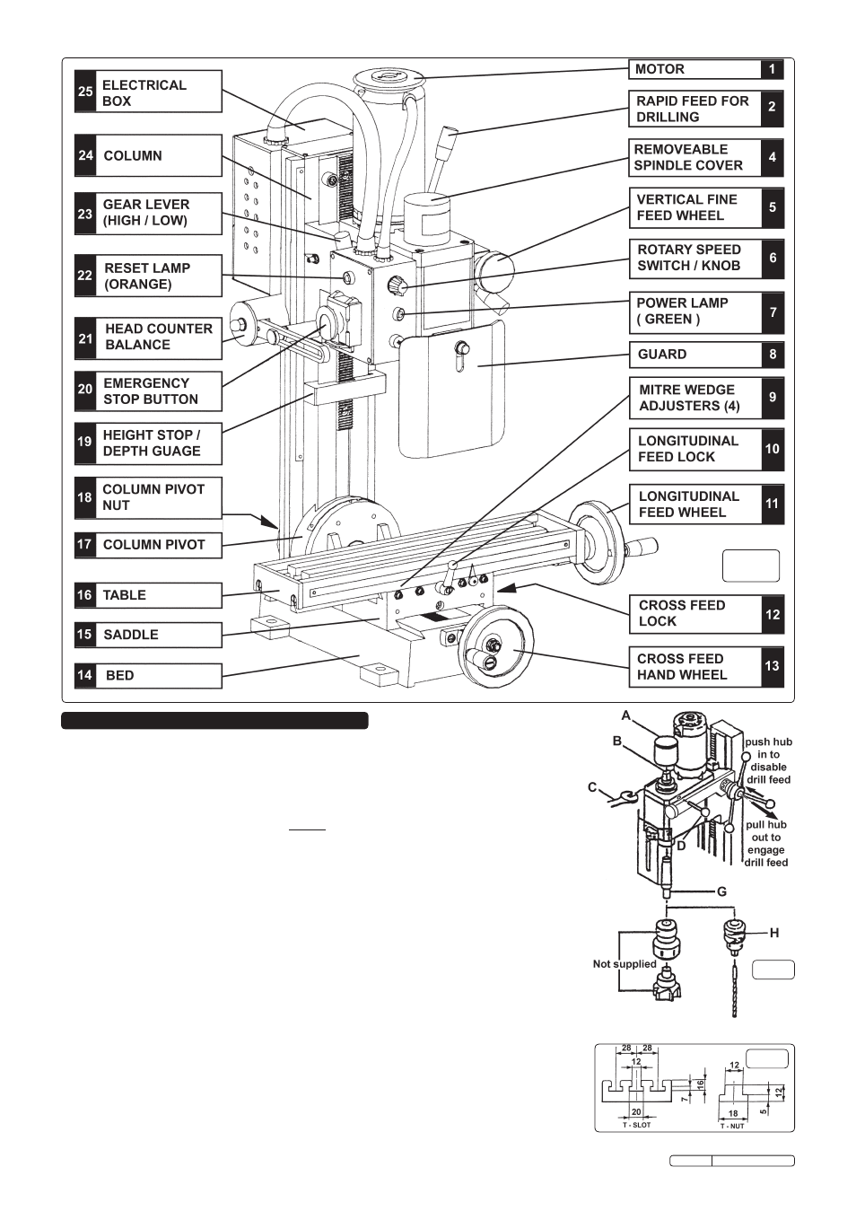
SeTTINg UP FOR MIllINg. (disconnect the machine from the power supply
while setting up.) the machine is supplied without milling attachments. (See section 8 for
details.) contact your local Sealey dealer for a full range of accessories.
4.1
engaging vertical fine feed. Prior to milling, activate the fine feed wheel ( see fig.3-5 )
by pushing the drill feed hub inwards toward the body of the machine so that the two sets
of castellations on the hub shaft engage together and lock the movement of the drill feed.
( See fig.4 ) this action automatically engages the fine feed wheel. Set the depth stop to
its maximum so that it does not interfere with downward movement when setting the
height of the milling tool. ( See fig.3-19 )
4.2
Mounting the Cutting Tool. If the drill chuck and arbor are currently mounted, remove
them by loosening the nut on the arbor bolt by two turns and giving it a tap with a rubber
mallet. (the arbor bolt appears at the top of the spindle shaft and can be accessed by
pulling off the plastic cap. See figs.3-4 and 4-A ) ensure that the drill chuck and arbor are
supported as they are removed.
4.2.1 Select the cutting tool for the work in hand and the appropriate arbor or collet.
Wear
protective gloves at all times especially when handling the cutter. Introduce the
cutter assembly into the spindle sleeve and hold it in place whilst the arbor nut and bolt
are tightened by hand. Insert the locking pin provided into the hole in the right hand side of
the head adjacent to the spindle
( See fig.4-d ) to prevent the spindle rotating. tighten the arbor bolt with a spanner ( do not
overtighten ). remove the locking pin and replace the plastic cap.
4.3
Attaching the workpiece. the main bed of the machine has 3 inverted ‘t’ slots in it for
fixing the workpiece or any vice/clamping arrangement used to hold the workpiece. the
dimensions of the ‘t’ slots and ‘t’ nuts are shown in fig.5. A 42 piece clamping kit is available
as an optional extra. Part no. SM2502cK.
4. SeT- UP ANd OPeRATION
fig. 3
fig.4
fig.5
Original Language Version
SM2502 Issue: 2 - 17/12/09