Sealey HFC08 User Manual
Pneumatic filter crusher, Hfc08.v2, Fig.1
INSTRUCTIONS FOR:
PNEUMATIC FILTER CRUSHER
MODEL NO:
HFC08.V2
Important: REAd THESE INSTRUCTIoNS CAREFULLy. NoTE THE SAFE oPERATIoNAL REQUIREMENTS, WARNINGS ANd CAUTIoNS. USE
THIS FILTER CRUSHER CoRRECTLy ANd WITH CARE FoR THE PURPoSE FoR WHICH IT IS INTENdEd. FAILURE To do So MAy
CAUSE dAMAGE ANd/oR PERSoNAL INjURy ANd WILL INVALIdATE THE WARRANTy. RETAIN THESE INSTRUCTIoNS FoR FUTURE USE.
Thank you for purchasing a Sealey product. Manufactured to a high standard this product will, if used according to these instructions
and properly maintained, give you years of trouble free performance.
1. SAFETy INSTRUCTIoNS
2. INTRodUCTIoN & SPECIFICATIoN
3. ASSEMbLy
WarnInG! Wear protective gloves and approved safety eye protection (standard spectacles are not adequate).
WarnInG! Ensure Health & Safety, local authority, and general workshop practice regulations are adhered to when using this equipment.
do NoT allow untrained persons to use the filter crusher.
do NoT operate the filter crusher when you are tired or under the influence of alcohol, drugs or intoxicating medication.
do NoT operate the filter crusher if parts are damaged or missing as this may cause failure and/or personal injury.
do NoT use the filter crusher for a task it is not designed to perform.
do NoT crush aerosol cans, cylinders of compressed gas, fuel filters or containers of flammable liquids or solvents.
do NoT smoke when using crusher.
do NoT modify the crusher or alter the operation in any way to circumvent the interlocking door mechanism.
Place oil filters into the crushing chamber open side down.
Maintain the filter crusher in good condition. Replace or repair damaged parts. Use genuine parts only. Unauthorised parts may be dangerous
and invalidate the warranty.
Familiarise yourself with the applications, limitations and potential hazards of the filter crusher.
Keep work area clean, uncluttered and ensure there is adequate lighting.
Maintain correct balance and footing. Ensure the floor is not slippery and wear non-slip shoes.
Keep the filter crusher clean for best and safest performance.
When not in use release pressure from the filter crusher.
Wear appropriate clothing such as overalls.
Keep untrained/unauthorised personnel away from filter crusher.
Clean up any spilled oil immediately so it will not cause a slipping hazard.
If the unit has to be re-sited it should be moved with the crushing module in the lowered position.
2.1 Introduction.
Reduce your waste disposal costs* - crushing filters minimises the volume of your hazardous waste. Air operated oil filter press with safety lock-out
device which prevents the door being opened during operation. Floor mounting unit with outlet for waste oil transfer.
* For disposal by volume customers.
2.2 Specification.
Max. Filter Capacity (H x D): . . . . . . . . . . . . . . . . . . . 216mm x 152mm
External Dimensions (H x W x D): . . . . . . . . . . . . 880 x 550 x 335mm
Internal Dimensions (H x W x D). . . . . . . . . . . . . . . . . 280 x 190 x 190
Air Supply: . . . . . . . . . . . . . . . . . . . . . . . . . . . . . . . . . . . . . . 100-190psi
Capacity: . . . . . . . . . . . . . . . . . . . . . . . . . . . . . . . . . . . . . . . . . . . .10ton
Pressing Time: . . . . . . . . . . . . . . . . . . . . . . . . . . . . . . . . . . . . . . . 30sec
WarnInG! The unit is very heavy and should only be moved with a
crane or forklift truck.
3.1 Location and Assembly
Locate the crusher in a suitable place indoors on firm and level
concrete.
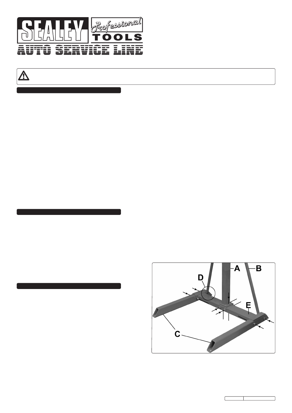
3.1.1 Firstly the stand must be assembled. Attach the two legs (Fig.1C) to
the cross beam (Fig.1E) using two bolts washers and nuts either side.
Ensure that upright supports (Fig.1B) are secured with the far nut
(Fig.1D) on each leg.
3.1.2 Place the upright on the crossbeam (Fig.1E) aligning with the
pre-drilled holes. Ensuring it is the correct way around with the lip over
the back of the cross beam. Secure with two bolts, washers and nuts
vertically through the cross beam and two horizontally through the lip
of the upright.
3.1.3 Secure the upright supports (Fig.1B) already attached to the legs (Fig.1D), to the upright using a bolt, nut and washer part way up the
upright (not in picture).
3.1.4 The unit must be bolted to the floor with four 1/2" anchor bolts, one at each end of the legs. This must be before the crushing unit is secured.
3.1.5 A fork lift truck or suitable crane should be used to raise the unit to its operational position. Remove the large nut and bolt from upper part of
the upright. Slide the mounting collars on the back of the crushing module onto the upright and align the holes in the upper collar with the
holes in the upright and insert the large bolt and secure with the nut provided.
3.1.6 The oil collection tray has a 1/2” hose adaptor on its underside so the unit can be plumbed into a remote waste oil container.
HFC08.V2 Issue: 1 - 25/06/09
Fig.1