Sealey GA40 User Manual
Page 3
Sole UK Distributor, Sealey Group,
Bury St. Edmunds, Suffolk.
NOTE:
It is our policy to continually improve products and as such we reserve the right to alter data, specifications and component parts without prior notice.
IMPORTANT: No liability is accepted for incorrect use of this product.
WARRANTY: Guarantee is 12 months from purchase date, proof of which will be required for any claim.
INFORMATION: For a copy of our latest catalogue and promotions call us on 01284 757525 and leave your full name and address, including postcode.
01284 757500
www.sealey.co.uk
01284 703534
Web
5.2.3 Stand the periscope unit on a level floor approximately 1metre ahead of the front bumper with the target plate facing the mirror. This is
the set up shown in fig.5. With the pointer at zero, move the periscope unit until the hair line bisects the triangle as in fig. 2.
5.2.4 Without moving the periscope unit, transfer the mirror unit to the next axle ( X in fig.5 ) and check the reading. This should be identical
to axle Y. If not then the rear axles are not parallel and will require adjustment.
5.2.5 Position mirror unit at axle A and check reading. If the original setting was parallel, the hair line should be central on the target plate.
For a toe in setting, move the pointer until it shows half the amount of the recommended toe-in ( e.g. a 20 movement for a 40 toe-in ).
The hair line should now be in the central position on the target plate. If not, gently turn the steering wheel, keeping the contact bars
positioned on the rim or the tyre sidewall until the hair line is central. Axle A is now correctly aligned with the rear axles.
5.2.6 Move the mirror unit to axle B and note the reading in comparison to axle A.
5.2.7 If the reading is different the inter-axle adjuster will need adjustment, recheck from step 5.2.2 onwards.
5.2.8 To compensate for run-out in tyres and/or wheels roll the vehicle forward until the wheels have rotated half a revolution (180
0
). Repeat
steps 5.2.2 to 5.2.6. Should the results vary, average the figures obtained. Adjust the connecting rods as necessary until the hair line
appears central.
5.2.1 Check alignment of the two pairs of front axle wheels ( A & B in fig.5 ) in the same way as you would for cars including the calibration
procedure. Adjust if required to the manufacturers recommendations or set to parallel.
5.2.2 Replace normal mirror unit with the larger mirror unit. Place this unit against the last axle ( Y in fig.5 ) with the mirror orientated towards
the front of the vehicle.
GA40 - 1 - 080304
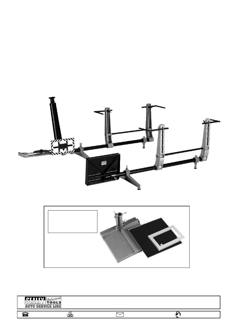
Optional equipment consisting of
a larger size mirror and a target
plate enlargement frame.
Order Item: GA43