Sealey VS710 User Manual
Page 2
Original Language Version
VS710 Issue No.1 30/10/09
2. INSTRUCTIONS
2.1 Raise the vehicle and ensure that it is adequately supported before beginning work.
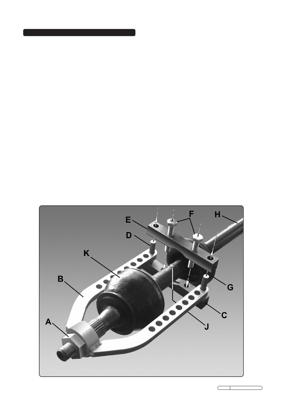
2.1.1 Referring to the manufacturer's servicing manual, dismantle the suspension/wheel hub as
directed until the outer end of the drive shaft (H) is free and accessible as shown below.
2.1.2 Detach the rubber boot (G) from the back of the constant velocity joint (K) and slide it up the
drive shaft. Clean the grease from the joint and the drive shaft especially in the grooved/
shouldered area (J).
2.2 Assemble the tool to the drive shaft as follows:
2.2.1 Take the main tool (B) and slide the ring over the end of the drive shaft so that the arms lie
either side of the constant velocity joint and at least 5mm of the threaded end of the shaft
lies within the ring.
2.2.2 Take the lower clamp (C) and insert the two pins (D) through the holes in the clamp arms so
that the clamp touches the drive shaft within the grooved/ shouldered area (J).
2.2.3 Lower the upper clamp (E) over the lower clamp pins (D). Insert the two bolts (F) and thread
them into the lower clamp as shown below and tighten equally until the tool is firmly
attached to the drive shaft.
2.2.4 Screw the hub nut (A) onto the end of the drive shaft until it faces onto the ring. Do not
tighten yet.
2.3 Releasing joint retained by sprung ring (no circlip).
2.3.1 Gradually tighten the hub nut to compress the sprung ring. Continue winding the hub nut
until the joint is released.
2.4 Releasing joint retained by a circlip.
2.4.1 Where the joint is retained by a circlip it will be necessary to compress the clip using a
suitable tool. Keep the circlip under tension whilst winding the hub nut until the joint is
released.
2.5 Disassemble the tool from the drive shaft and remove the joint.
- VS0288 RE99/09 RE99/10 PS982 HP10 HP5 PS990 VS0286 VS1270 VS0285 VS7021 SX0406 SA28 SA200T DFS55 RE55 WS680 WS681 WS650 WS570 SM14 SA57 SG16 GSA53 SA56 SA92 GSA6000 SA4 SA602L SA6001 SA686 SA681 SA680 SA682 SA291 SA6005 GSA02 GSA01 SA655 SA29/S SA297 GSA6002 SA51 SA660 SA50 SA661 MK58 VS0041 VS726 VSE127H05 MK51 SA912 SA616 SA615 GSA07 GA450 GA45 VS392 VSE725 TL93 S01047 SA26 SA27 VS1274 AP22505BB GV180WM AP2200BB MS900PSEU VS0287