Fig.3, Operating instructions – Sealey POWERSTART200 User Manual
Page 3
WARNING! YOU MUST FOLLOW SAFETY INSTRUCTIONS AND ENSURE THAT THE POWERSTART AND VEHICLE VOLTAGES ARE THE
SAME.
5.1.
Before use, press the test button to confirm that the Powerstart is charged (see 4.1.).
5.2.
Apply the vehicle hand brake and select neutral gear (or ‘Park’ if automatic transmission). Turn ignition and electrical accessories off.
5.3.
Use in a well ventilated area and wear protective eye shields and clothing.
WARNING! Do not allow the red and black clamps to touch each other once the leads are connected to the Powerstart. Ensure that
the correct clamps are placed on the correct battery terminals.
5.4.
With the leads
disconnected from the Powerstart attach the positive RED (+) clamp to the positive terminal on the vehicle battery.
Ensure that the terminal is clean.
Note: On vehicles with multiple batteries connect positive clamp to positive battery terminal which is connected to vehicle electrical
system.
5.5.
Attach the negative BLACK (-) clamp to the (ground) engine block or frame of the vehicle. Ensure that the cables are not in the path of
moving engine parts, such as the fan and are away from the carburettor/injection system, fuel lines etc.
5.6.
The lead plug on the POWERSTART200 and 350 is fitted with a polarity indicator. Confirm that the green LED is illuminated.
If the red LED is illuminated then the clamps are cross-connected and MUST be reversed.
5.7.
With the Powerstart control switch (fig.1.D & fig.2.D) set to ‘Off’ plug the leads into the socket (fig.1.C or fig.2.C).
Note: The connector will only fit the socket one way round, to prevent cross-connection.
5.8.
On models POWERSTART350 POWERSTART500 AND POWERSTART900 turn the control switch (fig.2.D) to select 12 or 24V to
match the vehicle voltage. On the Powerstart350 to select 24V the switch knob must be pulled out and then turned.
On model POWERSTART200 turn the switch (fig. 1.D) to select 12V.
5.9.
Make sure that no one is standing near the battery. When all is OK, start the engine.
5.10. Once the vehicle has started, turn the control switch to ‘Off’ and then disconnect the leads from the Powerstart.
5.11. To the lead clamps firstly disconnect the BLACK (-) negative clamp followed by the RED (+) positive clamp.
5.12. IMPORTANT: If the vehicle does not start within six seconds, DO NOT continue cranking. Let the Powerstart’s internal battery(ies) cool for
three minutes before attempting to start the vehicle again. Failure to do
so may damage the unit.
5.13. After use, immediately recharge the Powerstart as described in 4.2.
WARNING! BEFORE CHARGING THIS UNIT, DISCONNECT THE
OUTPUT LEADS FROM THE UNIT AS THEY WILL REMAIN “LIVE”
WHILE CHARGING.
WARNING! NEVER CLAMP THE OUTPUT LEADS TO THE CARRY
HANDLE AS THIS COULD RESULT IN SHORT CIRCUIT.
WARNING! The warnings, cautions and instructions discussed in
this manual cannot cover all possible conditions and situations
that may occur. It must be understood that common sense and
caution are factors which cannot be built into this product, but
must be applied by the operator.
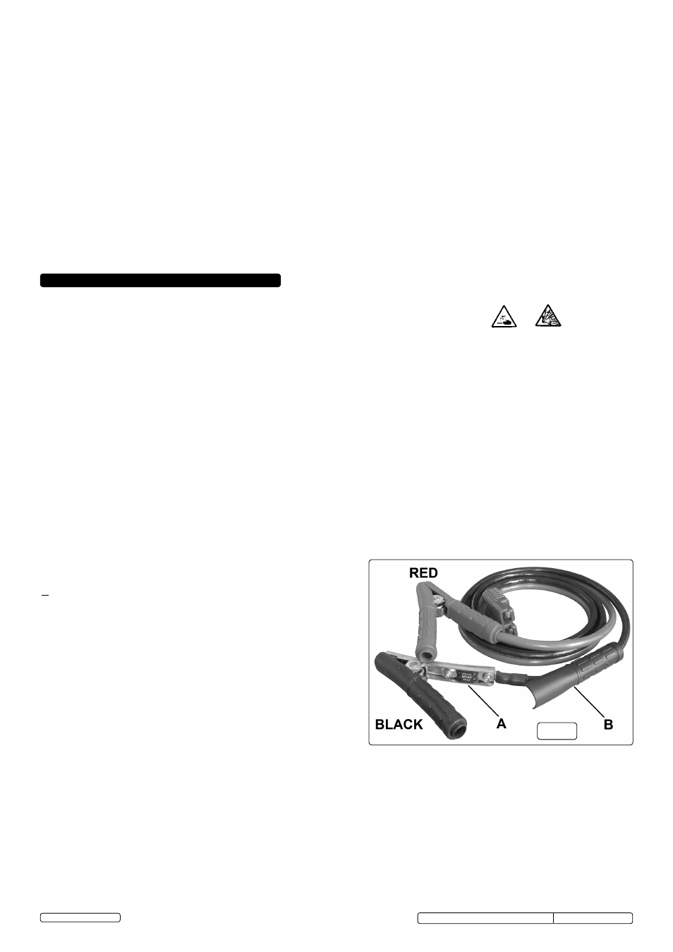
5.14. On POWERSTART500.V2 and 900 models, the negative BLACK
clamp is fitted with a 500A fuse within the black sleeve. (fig.3A).
Before accessing this fuse, turn the switch knob to OFF and unplug
the power leads from the unit. Work the black sleeve down into the black
lead. See fig.3B. After replacing the fuse ensure the black sleeve fully covers the clamp.
5. OPERATING INSTRUCTIONS
fig.3
4.2. Recharging
When new the unit should be charged before use until the charger display indicates
"Full".
WARNING! Use the supplied charger, cable and connector. Unauthorised parts may damage the unit and will invalidate the warranty.
Ensure that you strictly apply the safety instructions as stated in Section 3.
4.2.1. Ensure that the Powerstart control switch (fig.1.D) is in the ‘Off’ position.
4.2.2. Plug the charger mains cable into a 230 volt supply. The green ‘On’ LED will illuminate.
4.2.3. Plug the charger cable into the charge input socket (fig.1.B) of the unit. The unit will now charge automatically and the charger LED's will
indicate the level of charge. When the green ‘Full’ LED comes on, charging is complete but the charger should not be disconnected or
switched off.
Leave it connected to the Powerstart to ensure that the unit is fully charged when next required.
4.2.4. To disconnect the charger from the Powerstart, first switch off the charger, then press and hold the latch immediately above the socket and
pull out the plug.
Important! If the ‘Fault’ LED on the charger illuminates, switch off the charger, disconnect it from the Powerstart and contact your Sealey dealer.
Note: The POWERSTART charging circuits are protected against short circuit by thermal breakers.
The breaker in the POWERSTART200 has automatic reset whilst those in the POWERSTART350, POWERSTART500 and
POWERSTART900 (two in each - one per battery) have manual reset buttons on the front panel.
Original Language Version
POWERSTART200 / 350 / 500.V2 / 900 Issue: 6(SP) - 25/09/13
© Jack Sealey Limited