Sealey TA102 User Manual
Ta102, 11 function digital automotive analyser, Instructions for
1.1.PERSONAL PRECAUTIONS
When using the analyser, please observe all normal safety rules concerning
:
Protection against the dangers of electric current.
Protection of the analyser against misuse.
Full compliance with safety standards can only be guaranteed if used with the test leads supplied. If necessary, these must be replaced with genuine
Sealey leads with the same electronic ratings. Failure to do so will invalidate the warranty.
DO NOT use leads if damaged or if the wire is bared in any way.
1.2. GENERAL SAFETY INSTRUCTIONS
Familiarise yourself with the application and limitations of the analyser as well as the potential hazards. IF IN ANY DOUBT CONSULT A QUALIFIED
ELECTRICIAN.
When the analyser is linked to a measurement circuit, do not touch unused analyser terminals.
When the scale of the value to be measured is unknown set the selector to the highest range available.
Before rotating the function dial to change functions, disconnect test leads from the circuit under test.
WARNING! Never perform resistance measurements on live circuits. Only measure on disconnected circuits.
Use caution when working with voltages above 60V DC or 30V AC. Keep fingers behind the probe barriers whilst measuring.
When not in use, store the analyser carefully in a safe, dry, childproof location. Storage temperature range -10°C to 50°C.
Never apply voltage or current to the analyser that exceeds the specified maximum.
WARNING! DO NOT make current measurements on the 10A scale for longer than 15 seconds in every 15 minutes.
Exceeding 15 seconds may cause damage to the analyser and test
leads.
INStrUCtIONS FOr:
11 FUNCTION DIGITAL AUTOmOTIvE ANALYSER
MODEL No:
TA102
2. INTRODUCTION
1. SAFETY
Functions
Function
Test Range
AC Voltage
200mV - 1000V
200Ω − 20MΩ
3cyl 120°- 8cyl 45°
180 - 10000rpm
20mA - 10A
-20°C to 750°C
-4°F to 1382°F
Vce=3V,
I
b=10µA
typically 1mA
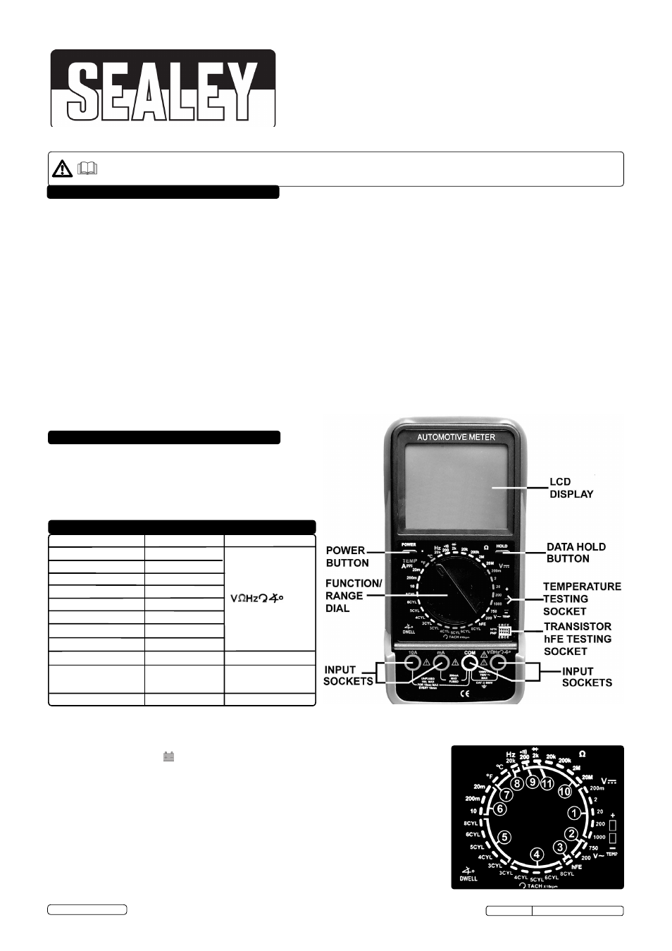
Large, hi-contrast LCD display with 34mm high digital read-out. Durable
bi-composite case and integral stand, suitable for the toughest
workshop conditions. test Lead Connection feature indicates correct
hook-up. Includes over-ranging, auto-zeroing, data hold, auto power-off
and low battery display functions. Supplied with capped test probes and
K-type thermocouple.
C o n n e c t i o n s
Frequency
Diode test
Continuity test
DC Current
<30 Ohms
20kHz
tachometer
temperature
transistor test (hFE)
resistance
Dwell Angle
200V - 750V
DC Voltage
+COm
mA or 10A + COm
Temp. sockets &
thermocouple
Transistor socket
maximum Display:
1999 counts - (3 1/2 digits) LCD display with automatic polarity indication.
measurement Rate:
2-3 times per second.
measuring method:
Dual-slope integration A/D converter system.
Over Range Indication: Figure “1” displayed on the LCD.
Low Battery Indication: the symbol is displayed when the battery voltage drops below the operating level.
Auto-Power-Off:
Meter automatically shuts down after approx. 15 minutes of inactivity.
Operating Environment: 0°C to 40°C (32°F to 104°F) at <75% relative humidity.
Storage Environment:
-10°C to 50°C (14°F to 122°F) at <75% relative humidity.
Power:
Single standard 9 Volt battery (PP3).
Fuse: 250mA/250V.
Dimensions:
200 x 97 x 48 mm.
Weight Approx:
495g including battery and holster.
1.
DC voltage
2.
AC voltage
3.
Transistor Check
4. Tachometer
5.
Dwell Angle
6.
DC Current
7. Temperature
8. Frequency
9.
Audible Continuity Check
10. Resistance
11. Diode check
Function Guide (Fig.2)
Fig.1
Fig.2
IMPORTANT: PLEASE READ THESE INSTRUCTIONS CAREFULLY. NOTE THE SAFE OPERATIONAL REQUIREmENTS, WARNINGS & CAUTIONS. USE THE
PRODUCT CORRECTLY AND WITH CARE FOR THE PURPOSE FOR WHICH IT IS INTENDED. FAILURE TO DO SO mAY CAUSE DAmAGE AND/OR
PERSONAL INJURY AND WILL INvALIDATE THE WARRANTY. KEEP THESE INSTRUCTIONS SAFE FOR FUTURE USE.
Thank you for purchasing a Sealey product. manufactured to a high standard, this product will, if used according to these
instructions, and properly maintained, give you years of trouble free performance.
the user shall ensure that test probes are correctly selected in order to prevent danger. Probes shall be selected to ensure that adequate barriers guard against
inadvertent hand contact with live conductors under test and that probes have minimal exposed probe tips. Where there is a risk of the probe tip short circuiting
with other live conductors under test, it is recommended that the exposed tip length shall not exceed 4mm.
© Jack Sealey Limited
tA102 Issue No: 4(I) - 16/06/14
Original Language Version