Control panel, Operating modes – Sealey ECS350 User Manual
Page 4
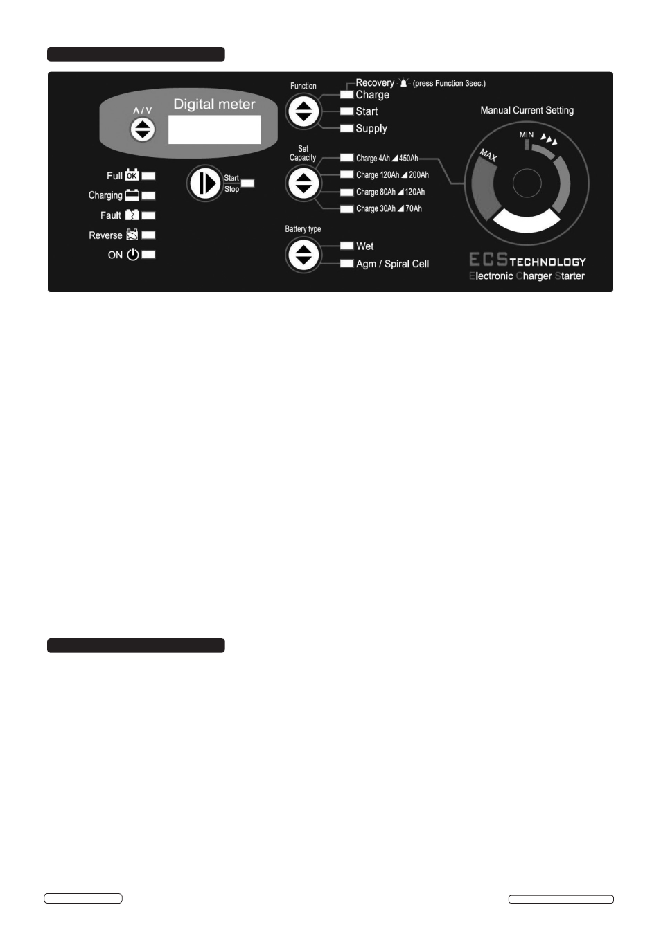
5. CONTROL PANEL
5.1.
Signalling LEDs.
There are 15 LEDs on the front panel having the following functions:
• 4 battery status LEDs, indicating:
Full: . . . . . . . . . . . . . . . . . . . . . . . . . . . . . . . . battery is charged and is in Charge Maintenance status.
Charging: . . . . . . . . . . . . . . . . . . . . . . . . . . . . battery charging.
Fault: . . . . . . . . . . . . . . . . . . . . . . . . . . . . . . . battery is damaged.
Reverse:. . . . . . . . . . . . . . . . . . . . . . . . . . . . . polarity reversal.
• 1 battery charger status LED: . . . . . . . . . ON LED, battery charger ON (colour BLUE).
• 1 operating status LED: . . . . . . . . . . . . . . indicates whether output is in accordance with selected mode.
. . . . . . . . . . . . . . . . . . . . . . . . . . . . . . . . . . . . Correlated with the Start/Stop button (Colour YELLOW).
• 3 LEDs on Function operating mode: . . . Charge, Start or Supply (colour YELLOW)
• 4 battery capacity indication LEDs:. . . . . Set Capacity described in section 6.2. (colour YELLOW).
• 2 battery type indication LEDs: . . . . . . . . Battery Type described in section 6.3. (colour YELLOW).
5.2.
Operating mode selection buttons
There are 5 buttons on the front panel which have the following functions:
• Start / Stop: . . . . . . . . . . . . . . . . . . . . . . . . starts or stops supply in the selected mode.
• Function: . . . . . . . . . . . . . . . . . . . . . . . . . . selects operating mode.
• Set Capacity: . . . . . . . . . . . . . . . . . . . . . . . selects battery capacity.
• Battery Type: . . . . . . . . . . . . . . . . . . . . . . . selects the type of battery to charge.
• A/V: . . . . . . . . . . . . . . . . . . . . . . . . . . . . . . . selects the information to be displayed.
5.3.
Digital Display.
5.3.1.
A/V button: The A/V selector button selects voltage or current display or allows the user to change the display language. Pressing
the A/V button toggles from voltage display U to current display A, and finally the Language menu. This menu will show the message
“LANGUAGE = ITALIAN” or another language, depending on the selection.
5.3.2.
Change Display Language.
To enter the language selection mode, press the A/V button and hold it down when the display is showing the message
“LANGUAGE = ITALIAN”. The language setting is Italian by default; to scroll the language menu press the A/V button again and the
language shown will change instantly. Languages supported:
• Italian • English.
Once the language is set, to quit the menu press the A/V button for a few seconds.
6. OPERATING MODES
6.1. Function.
Note: All modes support both 12V and 24V batteries (voltages stated for 12V batteries).
6.1.1.
Charge Mode.
Battery charging mode. Provides 11 charging steps as described below:
• STEP 1: Analysis 1: If the battery output is less than 10.5V the unit proceeds with the next analysis. Outputs below 5V will cause the
charger to revert to stand-by.
• STEP 2: Analysis 2 (sulphated battery): The display shows the message “ANALYSIS” alternating with the instantaneous voltage
or current. After this step the unit either starts the charging cycle directly or it displays the message “SULPHATED
BATTERY” to inform the operator that the battery must be recovered.
• STEP 3: Desulphation: Pulsed voltage to prevent sulphation of the battery.
• STEP 4: Controlled current: Charges the battery up to the programmed limit value.
• STEP 5: Analysis 3 (elements short circuited): Checks whether the battery has short circuited elements or is damaged and
reports the error, if present.
• STEP 6: Deep Cycle Charging: Central charging cycle.
• STEP 7: Constant Voltage: Keeps the battery at the charging end voltage.
• STEP 8: Analysis 4:. Checks whether the battery has short circuited elements or is damaged and reports the error, if present.
• STEP 9: Trickle charging: Maintains the battery at 13.8V (WET) or 13.5V (AGM/SPIRAL CELL).
• STEP 10: Analysis 5: Checks whether the battery has short circuited elements or is damaged and reports the error, if present.
• STEP 11: Pulsed current cycle: Cycle that simulates the normal life cycle of the battery.
ECS350 Issue: 1 - 09/07/14
Original Language Version
© Jack Sealey Limited