Introduction & specifications 3. operation – Sealey AUTOCHARGE10 User Manual
Page 2
2.1. Introduction
Compact electronic battery chargers with pressed steel casings and carrying handle (not Autocharge 4). Intelligent charge control makes these
units perfect for long term maintenance of batteries on irregularly or seasonally used vehicles. Autocharge 10 additionally has selectable 6V or
12V charging. Suitable for lead-acid or low maintenance batteries, the chargers react continuously to battery condition and deliver whatever
charge rate is required. Reverse polarity protection prevents inadvertent damage to charger. LED indicators confirm the status of the charger
and an analogue ammeter (Autocharge5 &10 only) gives an accurate indication of charge rate. These electronic chargers can be connected to
a battery for an indefinite period - the intelligent circuitry constantly monitoring the voltage and maintaining the charge level at optimum.
2.2. Specifications
Model No: . . . . . . . . . . . . . . . . . AUTOCHARGE4 . . . . . . . . . . . . . . . . . .AUTOCHARGE5 . . . . . . . . . . . . . . . . AUTOCHARGE10
Output:. . . . . . . . . . . . . . . . . . . . . . . . . . . . 12Vdc . . . . . . . . . . . . . . . . . . . . . . . . . . 12Vdc . . . . . . . . . . . . . . . . . . . . . . . 6V/12Vdc
Output Current Peak(EN): . . . . . . . . . . . 4A(2.6A) . . . . . . . . . . . . . . . . . . . . . . . . 5A(3.5A) . . . . . . . . . . . . . . . . . . . . . . . . .10A(7A)
Input: . . . . . . . . . . . . . . . . . . . . . 230V 50Hz 58W . . . . . . . . . . . . . . . . . . 230V 50Hz 65W . . . . . . . . . . . . . . . . . 230V 50Hz 145W
Battery Range: . . . . . . . . . . . . . . . . . . . . .8-40Ah . . . . . . . . . . . . . . . . . . . . . . . . 10-50Ah . . . . . . . . . . . . . . . . . . . . . . . 20-100Ah
Ensure the output of the charger is the same voltage as the battery.
If battery has caps to access the battery fluid, remove the caps and check the fluid level before connecting the power clamps. If necessary
top-up the battery with distilled water by referring to the battery manufacturer’s instructions (Apply the personal safety precautions
described in part 1.2).
If the charger receives a sharp knock or blow the unit must be checked by a qualified service agent before using.
If the battery terminals are corroded or dirty clean them before attaching the power clamps.
Keep children and unauthorised persons away from the working area.
DO NOT dis-assemble the charger for any reason. The charger must only be checked by qualified service personnel.
DO NOT try to charge a non-rechargeable battery.
DO NOT try to start engine when charger is connected to battery.
DO NOT try to charge battery if battery fluid is frozen.
WARNING! To prevent the risk of sparking, short circuit and possible explosion DO NOT drop metal tools in the battery area, or allow them
to touch the battery terminals.
DO NOT allow power clamps to touch each other or to make contact with any metallic part of the vehicle.
DO NOT cross connect power leads from charger to battery. Ensure positive (+/RED) is to positive and negative (-/BLACK) is to negative.
DO NOT pull the cables or clamps from the battery terminals.
DO NOT use the charger outdoors, or in damp, or wet locations and DO NOT operate within the vicinity of flammable liquids or gases.
DO NOT use charger inside vehicle or inside engine compartment.
Ensure there is effective ventilation to prevent a build-up of explosive gases, and do not cover or obstruct charger ventilation louvres.
DO NOT use the charger for a task for which it is not designed.
WARNING! DO NOT simultaneously charge batteries of different capacities or discharge levels.
WARNING! If a fuse blows, ensure it is replaced with an identical fuse type and rating. Use only Sealey genuine parts.
When not in use, store the charger carefully in a safe, dry, childproof location.
2. INTRODUCTION & SPECIFICATIONS
3. OPERATION
WARNING! Ensure you read, understand and apply the safety and operational instructions before connecting the charger power
clamps to the battery. Only when you are sure that you understand the procedures is it safe to proceed with the actual charging
process.
Note: These electronic chargers can be connected to a battery for an indefinite period - the intelligent circuitry constantly monitoring the
volt age and maintaining the charge level at optimum.
Note: These units are fitted with a Thermal Fuse which will switch the charger off if the battery draws too large a current for too long a period
of time or in the event of high ambient temperature. Should this occur the unit must be returned to your local dealer for re-setting.
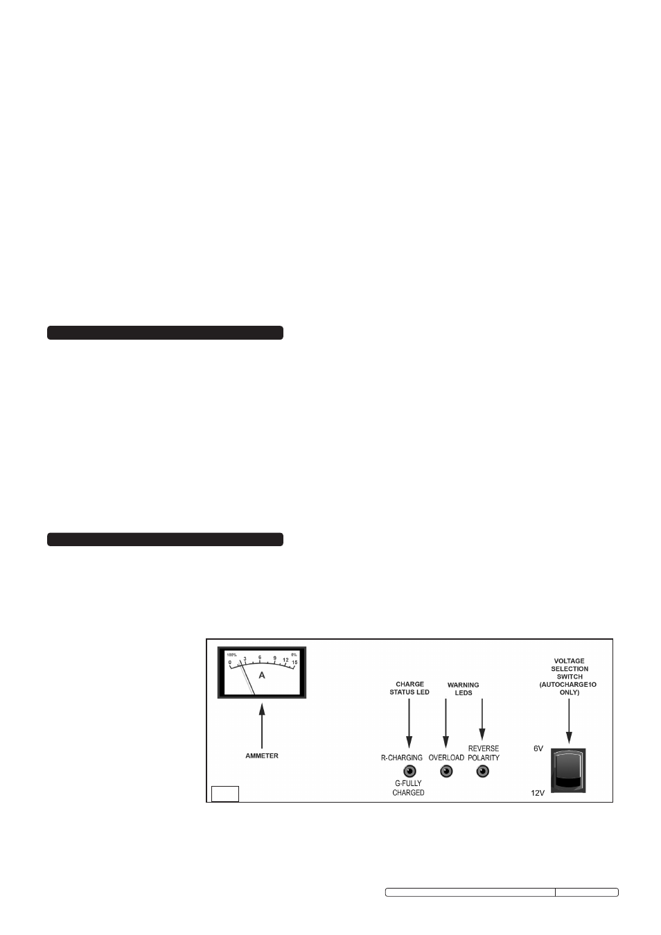
3.1. FRONT PANEL FACILITIES.
(See Fig.1)
Ammeter: When the unit is
plugged in to the mains supply
and connected to a battery the
ammeter indicates the level of
charge being delivered to the
battery. Where a battery is in a
low state of charge the needle
will be over to the right (or in the
red zone). As charging
continues the needle will move
to the left to ‘0’ (or be in the
green zone) indicating that the
battery is fully charged).
Charge Status LED: This is a dual colour LED. Whilst the battery is charging it is red. When the battery has reached full charge the
LED will turn green.
Warning LEDs: Should an overload occur the ‘OVERLOAD’ LED will illuminate red. If the polarity is reversed (i.e. the battery clamps
have been put onto the wrong terminals) the ‘REVERSE’ LED will illuminate red.
If either condition occurs, immediately unplug the
charger. Do not reconnect the charger until the reason for the condition has been understood and resolved.
Voltage Selection Switch: Choose between 6 and 12 volt charging. (Only available on Autocharge10).
Fig.1.
Original Language Version
AUTOCHARGE4, AUTOCHARGE5, AUTOCHARGE10 Issue: 3 - 09/09/10