E-mail: [email protected] – Sealey S0550 User Manual
Page 2
2
SPECIFICATION
Model No.
S0550.V2
Output 6V Peak(EN). . . . . . . . . . . . . . . . . . . . . . . . . .8A(5.6A)
Output 12V Peak(EN). . . . . . . . . . . . . . . . . . . . . . . . .8A(5.6A)
Input.. . . . . . . . . . . . . . . . . . . . . . . . . . . . . . . . . . . . . 230V 0.5A
Robust battery charger suitable for home and light workshop use. Features LEDs
to indicate the level of battery charge. 6 & 12V options with trickle and fast
charging modes. Composite housing with in-built carry handle. Internal protective
device for reverse polarity protection. 1.3mtr cable complete with insulated clamps.
Supplied with BS approved non-rewireable plug.
3
OPERATION
WARNING! This charger is suitable only for lead Acid Batteries and should
not be used to re-charge Ni-Cd or other type of battery.
DO NOT charge batteries smaller than 20Ah or greater than 120Ah.
WARNING! Ensure you read, understand and apply the safety and
operational instructions before connecting the charger power clamps to the
battery. Only when you are sure that you understand the procedures is it safe
to proceed with the actual charging process.
3.1
BATTERY PREPARATION
Caution ! Ensure you wear appropriate personal protection
including safety goggles as some electrolyte spillage may occur during the
following procedure
It is advised before charging, to remove the battery from the vehicle to prevent
damage to sensitive on board equipment on your vehicle.
Caution ! Before removing or replacing your battery ensure you read the
vehicle handbook and carefully follow the instructions relating to battery
removal and fitting.
3.1.1
If the battery is not a sealed unit, remove the filler caps and check the
level of the electrolyte. If it is below the recommended level, top up using
distilled water.
DO NOT use tap water under any circumstances.
3.1.2
To prevent acid splashing during the charging process, replace the filler
caps but do not tighten them to allow gasses to escape.
3.1.3
If the battery is a sealed unit it is unnecessary to carry out these checks.
3.2
CONNECTION
3.2.1
To avoid sparks which could cause an explosion, ensure the charger is
disconnected from the mains supply before making or breaking
connections.
3.2.2
Connect the crocodile clips to the battery in the following order:
a) Connect positive charging lead (RED) to the positive post of the battery
(marked P or +).
b) Connect the negative lead (BLACK) to the negative post of the battery
(market N or -). It is important that the crocodile clips make good
contact with the battery terminals. If necessary use a small wire brush
to clean the terminals.
3.3
CROSS POLARITY AND SHORT CIRCUIT PROTECTION
3.3.1
The battery charger has an internal protective device, if the charger is
connected so that polarities are crossed or there is a short circuit, it will
shut off the charger. The charging LED's will light up then will turn off.
If this happens turn off the charger at the mains, remove the mains
plug and disconnect from battery removing the negative clip first. Leave
for a couple of minutes to allow the charger to cool down then re-connect
crocodile clips to battery as in 3.2.2. Insert the plug back into the mains
supply and continue charging the battery. The charger should be fully
operational.
3.4
CHARGING
The S0550.V2 has four charging options:
a: 6V
b: 12V
c: Trickle charge (2A), for smaller batteries or if you require a slow rate of
charge. Recommended for batteries in a low state of charge.
d: Fast (8A) charge, for larger batteries or batteries that require a quick
boost charge.
3.4.1
Set the 6/12V switch to match the voltage of the battery.
3.4.2
Select trickle or fast charge.
3.4.3
Plug the charger into the mains supply (230V AC only).
3.4.4
Switch on supply and the charger will commence the charging procedure.
3.4.5
The rate of charge will now be displayed on the panel of LEDs
on the front of the charger.
The larger the number of LEDs illuminated, the lower the charge state of
the battery and higher the current flowing into the battery. As the battery
charges, less current will be drawn and less LEDs will be lit. When the
battery is fully charged, no LEDs will be lit.
When a flat battery is initially connected to the charger, the charging rate
should build up quickly. As the battery becomes more charged the rate of
charge will drop, this is normal.
4
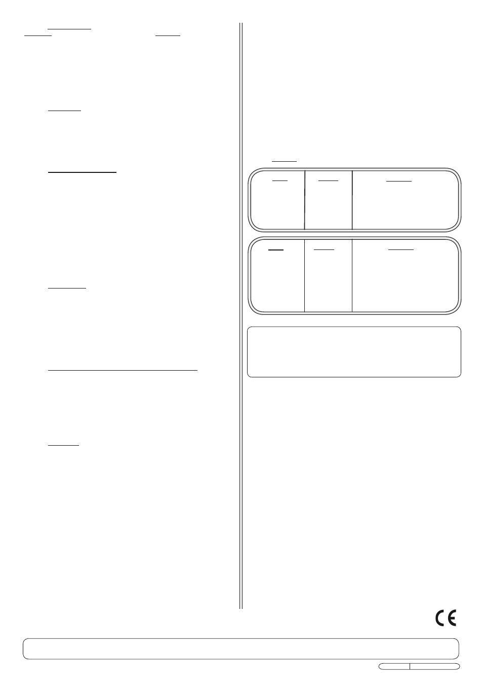
FAULTS
• Panel lights
fail to light.
• Panel lights
flicker and go
out.
• Switch
OFF
immediately at
the mains.
• Ensure the output leads are not
touching.
• Ensure the polarity is correct (RED
lead to + battery terminal, BLACK
lead to - negative terminal and .
When satisfied all is correct switch on
the mains and check again.
Fault
Fault
Action
Action
Remedy
Remedy
• Switch
OFF
immediately
at the mains.
• Ensure the output leads are not
damaged.
• Ensure the crocodile clips are
making good contact with the
battery posts, switch on the mains
and check again.
WARNING! Do not attempt to start the vehicle whilst connected to the
charger as this will damage the unit.
3.4.6
Regularly check the specific gravity of the electrolyte using a hydrometer,
until a reading of fully charged is reached.
A charging time of no more than 10 hours is recommended for batteries of
34 to 45 Ah capacity.
3.4.7
When charging is complete, switch of the mains supply. Unplug the
charger and disconnect the leads from the battery removing the negative
clip first. Inspect the electrolyte levels in each of the battery cells and top
up if necessary using distilled water. Replace the filler caps ensuring they
are fully tightened or pushed home. Any surplus fluid on the surface of the
battery should be wiped off (this should be done with extreme care as it
may be acidic).
WARNING! DO NOT use the charger if damaged or thought to
be faulty (Contact Service Agent).
When not in use, disconnect from the mains supply and store the
charger carefully in a safe, dry, childproof location.
NOTE: It is our policy to continually improve products and as such we reserve the right to alter data, specifications and component parts without prior notice.
IMPORTANT: No liability is accepted for incorrect use of this equipment. WARRANTY: Guarantee 12 months from purchase date, proof of which will be required for any claim.
E-mail: [email protected]
Sole UK Distributor, The Siegen Tool Co., Bury St. Edmunds, Suffolk
Original Language Version
S0550 .V2 Issue: 1 - 20/05/10